
Fluke 1625-2 KIT Advanced Geo Earth Ground Tester
- Advanced Geo earth ground testing with 3- and 4-pole measurement methods
- Internal memory storage for up to 1500 records via USB port
- Measures interference voltage and frequency alongside earth resistance
- 4-digit 7-segment LCD display with improved visibility
- IP56 rated case for durability in field conditions
- Operates on 6 x 1.5V alkaline batteries with up to 6000 measurements per charge
- Complies with DIN ISO 9001 quality standards and DIN 43780 for external field influence
- Secure Purchase
- Fast Delivery
- Genuine Guarantee
- Online Payment
Description
The Fluke 1625-2 KIT Advanced Geo Earth Ground Tester sets the standard for professional earth resistance measurement, delivering reliable performance for electrical engineers, field technicians, and maintenance teams who need to verify grounding system integrity. This comprehensive kit addresses the critical challenge of measuring earth resistance in environments where traditional methods fall short, combining advanced technology with Fluke’s renowned durability to ensure accurate readings across diverse installation conditions.
Fluke 1625-2 KIT Key Features
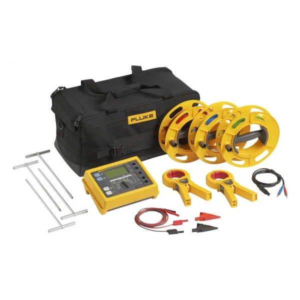
This versatile earth ground tester features multiple measurement methods including 3-pole, 4-pole, and clamp-on current transformer techniques, allowing users to select the most appropriate method for their specific site conditions. The internal memory stores up to 1500 resistance readings, accessible via USB port for data analysis and reporting. A clear 4-digit 7-segment LCD display ensures easy reading of measurements, while the IP56 rated case provides protection against dust and water ingress typical of field operations. The kit includes all necessary accessories for immediate deployment, making it an essential tool for grounding system verification.
- Interference voltage and frequency measurement capability
- 3-pole and 4-pole earth resistance measurement methods
- Clamp-on current transformer option for reduced test lead requirements
- 2-pole resistance measurement with AC and DC functionality
- Internal memory storage of 1500 records via USB
- 4-digit 7-segment LCD display for clear readouts
- IP56 rated case for field durability
- Operating temperature range -10°C to 50°C
Who Needs the Fluke 1625-2 KIT?
Electrical engineers and maintenance technicians responsible for grounding system commissioning and periodic testing will find the Fluke 1625-2 KIT indispensable for ensuring worker safety and code compliance. Power distribution facility managers rely on this kit to verify that grounding grids meet operational requirements and protect equipment from fault currents. Contractors and field service teams appreciate the kit’s versatility in handling various site conditions where standard 2-pole measurements are impractical or impossible due to limited access or soil conditions.
The Fluke 1625-2 KIT serves buyers ranging from large industrial facilities requiring regular grounding verification to smaller commercial operations needing occasional system checks. Utility companies use the kit for substation maintenance and new installation validation, while consulting engineers specify it for project specifications and compliance documentation. Any professional tasked with measuring earth resistance in challenging environments will benefit from the kit’s multi-method approach and reliable performance.
Fluke 1625-2 KIT Applications
New substation grounding grid testing ensures proper fault current path establishment before system energization, preventing equipment damage and ensuring personnel safety during fault conditions. Existing facility grounding system verification during routine maintenance identifies degradation, corrosion, or connection loosening that can compromise system effectiveness over time. The kit’s clamp-on method proves invaluable in space-constrained environments where driving test electrodes is impractical, such as inside buildings or paved areas.
Telecommunications tower grounding verification protects sensitive equipment from lightning strikes and power surges, while industrial plant grounding system testing ensures proper operation of protective relays and prevents nuisance tripping. The interference voltage measurement function helps identify stray currents that can affect sensitive electronic equipment, making this kit suitable for data centers, hospitals, and other facilities where power quality matters.
Why Buy Fluke 1625-2 KIT from Mohammad Mahdi Electronics?
Mohammad Mahdi Electronics ensures authentic Fluke products with manufacturer warranty coverage and genuine factory support for all testing equipment. Our team provides expert guidance to help you select the right earth ground tester for your specific application requirements and site conditions. We offer competitive pricing on Fluke 1625-2 KIT kits with fast shipping across the UAE and comprehensive after-sales support for calibration and maintenance services.
Choose Mohammad Mahdi Electronics for your Fluke 1625-2 KIT purchase and receive authentic products, knowledgeable service, and the reliability that comes from working with an MME who understands your testing needs.
General Specifications
Memory: Internal memory storage up to 1500 records accessible via USB port
Measuring function: Interference voltage and frequency, earthing resistance 3- and 4-pole with/without clip-on current transformer, resistance 2-pole with AC, 2- and 4-pole with DC
Display: 4 digit (2999 Digit) – 7 segment liquid crystal display, with improved visibility
Operation: Central rotary switch and function keys
Operating temperature: -10°C to 50°C (14°F to 122°F)
Storage temperature: -30°C to 60°C (-22°F to 140°F)
Temperature coefficient: ±0.1% of reading/°C < 18°C > 28°C
Type of protection: IP56 for case, IP40 for battery door according to EN60529
Max voltage: Warning – socket “clamp” to socket E, ES, S or H
U rms = 0 V
Sockets E, ES, S or H to each other in any combination, max. U rms = 250 V (pertains to misuse)
Safety: Protection by double and/or reinforced insulation. Max. 50 V to earth per IEC61010-1. Pollution degree 2
Quality standard: Developed, designed and manufactured to comply with DIN ISO 9001
External field influence: Complies with DIN 43780 (8/76)
Auxiliary power: 6 x 1.5 V alkaline (IEC LR6 or type AA)
Battery life span: With IEC LR6/type AA: typ. 3,000 measurements (R E +R H ≤ 1 kΩ)
With IEC LR6/type AA: typ. 6,000 measurements (R E + R H > 10 kΩ)
Dimensions (W x H x D): 250 x 133 x 187 mm (9.75 x 5.25 x 7.35 in)
Weight: ≤ 1.1 kg (2.43 lb) without accessories 7.6 kg (16.8 lb) incl. accessories and batteries in carrying case
Case material: Polyester
Measurement of Interference Voltage DC + AC (U ST )
Measuring limits of error: method: Full wave rectification
Measuring range: 1 V to 50 V
Display range: 0.0 V to 50 V
Resolution: 0.1 V
Frequency range: DC/AC 45 Hz to 400 Hz sine
Accuracy: ±(5% of rdg + 5 digit)
Measuring sequence: Approx. 4 measurements/s
Internal resistance: Approx. 1.5 MΩ
Max. overload: U rms = 250 V
Measurement of Interference Frequency (F)
Measuring limits of error: method: Measurement of oscillation period of the interference voltage
Measuring range: 6.0 Hz to 400 Hz
Display range: 16.0 Hz to 299.9 Hz to 999 Hz
Resolution: 0.1 Hz to 1 Hz
Range: 1 V to 50 V
Accuracy: ±(1% of rdg + 2 digit)
Earthing Resistance (RE)
Measuring method: Current and voltage measurement with probe as IEC61557-5
Open circuit voltage: 20/48 V, AC
Short circuit current: 250 mA AC
Measuring frequency: 94, 105, 111, 128 Hz selected manually or automatic. (AFC) 55 Hz in function R 1
Noise rejection: 120 dB (16 2/3 , 50
CT clamp-on current transformer: Model dependent, consult manual for compatibility
Accessories included: Carrying case, test leads, auxiliary electrodes, and user manual
Warranty: Standard Fluke international warranty through Mohammad Mahdi Electronics
CTA: Contact Mohammad Mahdi Electronics for technical specifications and pricing</
Stock up your testing lab with the Fluke 1625-2 KIT Advanced Geo Earth Ground Tester from Mohammad Mahdi Electronics. Our team is ready to assist you with product selection, warranty registration, and technical support for all your earth resistance testing needs. Contact our knowledgeable staff today to discuss how this versatile ground tester can meet your specific application requirements.
Fluke 1625-2 KIT Specifications
| General Specifications | ||||
| Memory | Internal memory storage up to 1500 records accessible via USB port | |||
| Measuring function | Interference voltage and frequency, earthing resistance 3- and 4-pole with/without clip-on current transformer, resistance 2-pole with AC, 2- and 4-pole with DC | |||
| Display | 4 digit (2999 Digit) – 7 segment liquid crystal display, with improved visibility | |||
| Operation | Central rotary switch and function keys | |||
| Temperature Range | ||||
| Operating temperature | -10°C to 50°C (14°F to 122°F) | |||
| Storage temperature | -30°C to 60°C (-22°F to 140°F) | |||
| Temperature coefficient | ±0.1% of reading/°C < 18°C > 28°C | |||
| Type of protection | IP56 for case, IP40 for battery door according to EN60529 | |||
| Max voltage | Warning – socket “clamp” to socket E, ES, S or H | |||
| Urms = 0 V | ||||
| Sockets E, ES, S or H to each other in any combination, max. Urms = 250 V (pertains to misuse) | ||||
| Safety | Protection by double and/or reinforced insulation. Max. 50 V to earth per IEC61010-1. Pollution degree 2 | |||
| Quality standard | Developed, designed and manufactured to comply with DIN ISO 9001 | |||
| External field influence | Complies with DIN 43780 (8/76) | |||
| Auxiliary power | 6 x 1.5 V alkaline (IEC LR6 or type AA) | |||
| Battery life span | With IEC LR6/type AA: typ. 3,000 measurements (RE+RH ≤ 1 kΩ) | |||
| With IEC LR6/type AA: typ. 6,000 measurements (RE + RH > 10 kΩ) | ||||
| Dimensions (W x H x D) | 250 x 133 x 187 mm (9.75 x 5.25 x 7.35 in) | |||
| Weight | ≤ 1.1 kg (2.43 lb) without accessories 7.6 kg (16.8 lb) incl. accessories and batteries in carrying case | |||
| Case material | Polyester | |||
| Measurement of Interference Voltage DC + AC (UST) | ||||
| Measuring limits of error: method | Full wave rectification | |||
| Measuring range | 1 V to 50 V | |||
| Display range | 0.0 V to 50 V | |||
| Resolution | 0.1 V | |||
| Frequency range | DC/AC 45 Hz to 400 Hz sine | |||
| Accuracy | ±(5% of rdg + 5 digit) | |||
| Measuring sequence | Approx. 4 measurements/s | |||
| Internal resistance | Approx. 1.5 MΩ | |||
| Max. overload | Urms = 250 V | |||
| Measurement of Interference Frequency (F) | ||||
| Measuring limits of error: method | Measurement of oscillation period of the interference voltage | |||
| Measuring range | 6.0 Hz to 400 Hz | |||
| Display range | 16.0 Hz to 299.9 Hz to 999 Hz | |||
| Resolution | 0.1 Hz to 1 Hz | |||
| Range | 1 V to 50 V | |||
| Accuracy | ±(1% of rdg + 2 digit) | |||
| Earthing Resistance (RE) | ||||
| Measuring method | Current and voltage measurement with probe as IEC61557-5 | |||
| Open circuit voltage | 20/48 V, AC | |||
| Short circuit current | 250 mA AC | |||
| Measuring frequency | 94, 105, 111, 128 Hz selected manually or automatic. (AFC) 55 Hz in function R1 | |||
| Noise rejection | 120 dB (16 2/3 , 50 , 60, 400 Hz) | |||
| Max. overload | Urms = 250 V | |||
| Electrical Measurement Specifications | ||||
| Intrinsic Error or Influence Quantity | Reference Conditions or Specified Operating Range | Designation Code | Requirements or Test in Accordance with the Relevant Parts of IEC 1557 | Type of Test |
| Intrinsic error | Reference conditions | A | Part 5, 6.1 | R |
| Position | Reference position ±90° | E1 | Part 1, 4.2 | R |
| Supply voltage | At the limits stated by the manufacturer | E2 | Part 1, 4.2, 4.3 | R |
| Temperature | 0°C and 35°C | E3 | Part 1, 4.2 | T |
| Series interference voltage | See 4.2 and 4.3 | E4 | Part 5, 4.2, 4.3 | T |
| Resistance of the probes and auxiliary earth electrodes | 0 to 100 x RA but ≤ 50 kΩ | E5 | Part 5, 4.3 | T |
| System frequency | 99% to 101% of the nominal frequency | E7 | Part 5, 4.3 | T |
| System voltage | 85% to 110% of the nominal voltage | E8 | Part 5, 4.3 | T |
| Operating error | B = ±(|A| + 1,15 √E21 E22 E23 E24 E25 E26 ) | Part 5, 4.3 | R | |
| B[%] = ± B/fiducial value x 100%
A = intrinsic error |
||||
| Measuring range | 0.020 Ω to 300 kΩ | |||
| Display range | 0.001 Ω to 2.999 Ω | |||
| 3.00 Ω to 29.99 Ω | ||||
| 30.0 Ω to 299.9 Ω | ||||
| 0.300 kΩ to 2.999 kΩ | ||||
| 3.00 kΩ to 29.99 kΩ | ||||
| 30.0 kΩ to 299.9 kΩ | ||||
| Resolution | 0.001 Ω | |||
| 0.01 Ω | ||||
| 0.1 Ω | ||||
| 1 Ω | ||||
| 10 Ω | ||||
| 100 Ω | ||||
| Accuracy | ±(2% of rdg + 2 digit) | |||
| Operating error | ±(5% of rdg + 5 digit) | |||
| Measuring time | Typical 8 seconds with a fixed frequency 30 sec. max. with AFC and complete cycle of all measuring frequencies | |||
| Additional error because of probe-and auxiliary earth electrode resistance | RH(RS + 2000 Ω)/RE x 1.25 x 10⁻⁶% + 5 digits | |||
| Measuring error of RH and RS | Typ. 10% of RE + RS + RH | |||
| Max. probe resistance | ≤ 1 MΩ | |||
| Max. auxiliary earth electrode resistance | ≤ 1 MΩ | |||
| Automatic check if error is kept within the limits required by IEC61557-5. If after a measurement of probe-, auxiliary earth electrode- and earthing resistance, a measurement error of higher than 30% is assumed because of the influencing conditions, the display shows a warning symbol and a notice that RS or RH are too high. |
||||
| Automatic Switchover of Measuring Resolution in Dependence to Auxiliary Earth Electrode Resistance RH | ||||
| RH with Umeas = 48 V | < 300 Ω | |||
| < 6 Ω | ||||
| < 60 Ω | ||||
| < 600 Ω | ||||
| RH with Umeas = 20 V | < 250 Ω | |||
| < 2.5 kΩ | ||||
| < 25 kΩ | ||||
| < 250 kΩ | ||||
| Resolution | 1 mΩ | |||
| 10 mΩ | ||||
| 100 mΩ | ||||
| 1 Ω | ||||
| Selective Measurement of the Earthing Resistance (RE Clamp) | ||||
| Measuring method | Current and voltage measurement with probe as per EN61557-5 and current measurement in the individual branch with additional current transformer (patent applied for). | |||
| Open circuit voltage | 20/48 V AC | |||
| Short circuit current | 250 mA AC | |||
| Measuring frequency | 94, 105, 111, 128 Hz selected manually or automatically (AFC), 55 Hz (R1) | |||
| Noise rejection | 120 dB (162/3, 50, 60, 400 Hz) | |||
| Max. overload | Max. Urms = 250 V (measurement will not be started) | |||
| Measuring range | 0.020 Ω to 300 kΩ | |||
| Display range | 0.001 Ω to 2.999 Ω | |||
| 3.00 Ω to 29.99 Ω | ||||
| 30.0 Ω to 299.9 Ω | ||||
| 0.300 kΩ to 2.999 kΩ | ||||
| 3.00 kΩ to 29.99 kΩ | ||||
| Resolution | 0.001 Ω | |||
| 0.01 Ω | ||||
| 0.1 Ω | ||||
| 1 Ω | ||||
| 10 Ω | ||||
| Accuracy | ±(7% of rdg + 2 digit) | |||
| Operating error | ±(10% of rdg + 5 digit) | |||
| Additional error because of probe- and auxiliary earth typ. electrode resistance | RH(RS + 2000 Ω)/RETOTAL x 1.25 x 10⁻⁶% + 5 digits | |||
| Measuring error of RH and RS | Typ. of 10% of RETOTAL + RS + RH | |||
| Measuring time | Typ. 8 sec. with a fixed frequency 30 sec. max. with AFC and complete cycle of all measuring frequencies. | |||
| Minimal current in single branch to be measured | 0.5 mA | With transformer (1000:1) | ||
| 0.1 mA | With transformer (200:1) | |||
| Max. interference current through transformer | 3 A | With transformer (1000:1) | ||
| 1. With recommended current clamps/transformers. | ||||
| Resistance Measurement (R~) | ||||
| Measuring method | Current and voltage measurement | |||
| Measuring voltage | 20 V AC, square pulse | |||
| Short circuit current | > 250 mA AC | |||
| Measuring frequency | 94, 105, 111, 128 Hz selected manually or automatically (AFC) | |||
| Measuring range | 0.020 Ω to 300 kΩ | |||
| Display range | 0.001 Ω to 2.999 Ω | |||
| 3.00 Ω to 29.99 Ω | ||||
| 30.0 Ω to 299.9 Ω | ||||
| 300 Ω to 2999 Ω | ||||
| 3.00 kΩ to 29.99 kΩ | ||||
| 30.0 kΩ to 299.9 kΩ | ||||
| Resolution | 0.001 Ω | |||
| 0.01 Ω | ||||
| 0.1 Ω | ||||
| 1 Ω | ||||
| 10 Ω | ||||
| 100 Ω | ||||
| Accuracy | ±(2% of rdg + 2 digit) | |||
| Operating error | ±(5% of rdg + 5 digit) | |||
| Measuring time | Typical 6 seconds | |||
| Max. interference voltage | 24 V, with higher voltages measurement will not be started | |||
| Max overload | Urms max. = 250 V | |||
| Resistance Measurement (R DC) | ||||
| Measuring method | Current- voltage measurement as per IEC61557-4 possible | |||
| Measuring voltage | 20 V DC | |||
| Short circuit current | 250 mA DC | |||
| Formation of measured value | With 4-pole measurement wires on H, S, ES can be extended without additional error. Resistances > 1 Ω in wire E can cause additional error of 5m Ω/Ω. |
|||
| Measuring range | 0.020 Ω to 300 kΩ | |||
| Display range | 0.001 Ω to 2.999 Ω | |||
| 3.00 Ω to 29.99 Ω | ||||
| 30.0 Ω to 299.9 Ω | ||||
| 300 Ω to 2999 Ω | ||||
| 3.0 kΩ to 29.99 kΩ | ||||
| 30.0 kΩ to 299.9 kΩ | ||||
| Resolution | 0.001 Ω | |||
| 0.01 Ω | ||||
| 0.1 Ω | ||||
| 1 Ω | ||||
| 10 Ω | ||||
| 100 Ω | ||||
| Accuracy | ±(2% of rdg + 2 digit) | |||
| Operating error | ±(5% of rdg + 5 digit) | |||
| Measuring sequence | Approx. 2 measurements/s | |||
| Measuring time | Typical 4 second including reversal of polarity (2-pole or 4-pole) | |||
| Maximum interference voltage | ≤ 3 V AC or DC, with higher voltages measurement will not be started | |||
| Maximum inductivity | 2 Henry | |||
| Maximum overload | Urms = 250 V | |||
| Compensation of Lead Resistance (RK) | ||||
| Compensation of lead resistance (RK) can be switched on in functions RE 3-pole, RE 4-pole (clamp), R AC, and R DC 2-pole | ||||
| Formation of measured value | Rdisplay = Rmeasured – Rcompensated2 | |||
| 2. Value of setpoint entry RK = 0.000 Ω, variable from 0.000 to 29.99 Ω by means of measuring adjustment. | ||||
| Stakeless Ground Loop Measurement (Two Clamp Stakeless) | ||||
| Switch position | RA 4-pole (two clamp Stakeless) | |||
| Resolution | 0.001 Ω to 0.1 Ω | |||
| Measuring range | 0.02 Ω to 199.9 Ω | |||
| Accuracy | ±(7% rdg + 3 digit) | |||
| Operating error | ±(10% rdg + 5 digit) | |||
| Measuring voltage | Vm = 48 V AC (primary) | |||
| Measuring frequency | 128 Hz | |||
| Noise current (IEXT) | Max. IEXT = 10 A (AC) (RA < 20 Ω) | |||
| Max. IEXT = 2 A (AC) (RA > 20 Ω) | ||||
| Measuring principle: Stakeless measurement of resistance in closed loops using two current transformers. Automatic range selection. The information regarding stakeless ground loop measurements is only valid when used in conjunction with the recommended current clamps at the minimum distance specified. |
||||
Datasheet
Datasheet
User Manual
User Manual
Reviews (0)
You must be logged in to post a review.
Bench Multimeters
Reviews
Clear filtersThere are no reviews yet.