

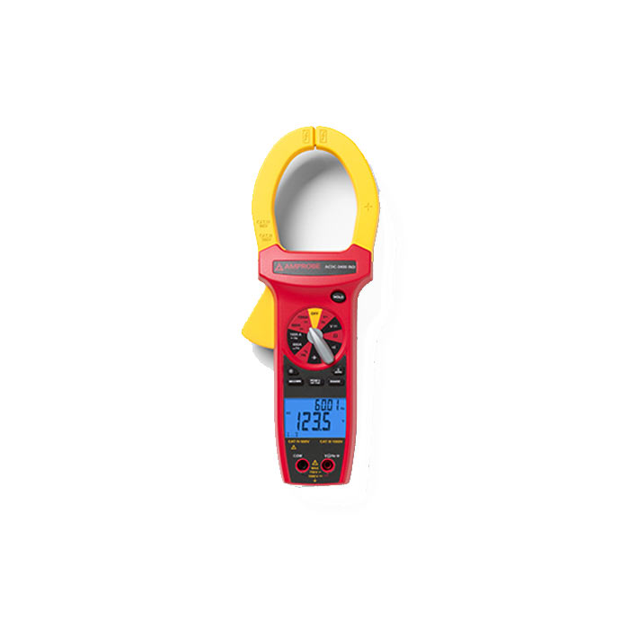
Amprobe ACDC-3400 IND AC/DC CAT IV TRMS Clamp Meter
Brand:
Amprobe
SKU:
94381-1-1-1-1
The Amprobe ACDC-3400 IND AC/DC CAT IV TRMS Clamp Meter stands out as a high-quality instrument that combines advanced technology, safety features, and a user-friendly design. It is a trusted choice for electrical industry professionals.
- Safe Buy
- Fast Delivery
- Original Guarantee
- Online Payment
Description
Amprobe ACDC 3400 IND
The Amprobe ACDC-3400 IND AC/DC CAT IV TRMS Clamp Meter is a sophisticated and reliable tool designed for professionals in various electrical fields, particularly in industrial and utility applications. This clamp meter is notable for its True RMS capability, which ensures accurate measurements even in complex electrical environments with non-sinusoidal waveforms.
Design and Build Quality
The Amprobe ACDC-3400 IND features a robust construction that meets the CAT IV safety rating, allowing it to be used in high-voltage scenarios. Its extra-large jaws can accommodate conductors up to 2 inches (51 mm) in diameter, making it versatile for various wire sizes. The ergonomic design enhances user comfort, especially during prolonged use, and the meter’s durable casing is built to withstand the rigors of everyday professional use.
Measurement Capabilities
This clamp meter is designed to measure both AC and DC currents, providing a comprehensive solution for electrical testing. It can handle high current measurements, making it suitable for heavy-duty applications. The inclusion of True RMS technology means that users can rely on accurate readings regardless of the waveform shape, which is crucial in modern electrical systems where loads may not always be purely sinusoidal.
Applications
The Amprobe ACDC-3400 IND is particularly beneficial for industrial electricians, HVAC technicians, and utility workers who require a dependable tool for monitoring electrical systems. Its ability to measure a wide range of electrical parameters makes it a valuable asset for troubleshooting, maintenance, and installation tasks.
Datasheet
Datasheet

Specifications
Specifications
| DC Volts | Ranges | Accuracy |
| 660.0 mV, 6.600 V, 66.00 V, 660.0 V, 1000 V | ± (0.5% rdg + 2 dgts) | |
| Input impedance | 660 mV: >100 MΩ; 6.6 V:10 MΩ; 66 V to 1000 V: 9.1 MΩ | |
| Overload protection | 1000 VDC or 750 VAC rms | |
| AC Volts True RMS | Ranges | Frequency |
| 660.0 mV | 50 to 100 Hz | |
| 6.600V, 66.00V | 50 to 500 Hz | |
| 660.0V, 750V | 50 to 500 Hz | |
| Frequency* | 50 to 1 kHz | |
| * Frequency: 10% to 100% of voltage range | ||
| Peak Hold | Ranges | Frequency |
| 66.00V, 660.0V, 750V | 50 to 500 Hz | |
| AC coupled TRMS | 5% to 100% of range | |
| Crest factor | ≤ 3 | |
| Input impedance | 660 mV: >100 MΩ; 6.6 V:10 MΩ; 66 V to 750 V: 9.1 MΩ | |
| Overload protection | 1000 VDC or 750 VAC rms | |
| AC Current True RMS | Ranges | Frequency |
| 660.0A | 50 to 60 Hz | |
| 660.0A | 61 to 400 Hz | |
| 1000 A | 50 to 60 Hz | |
| 1000 A | 61 to 400 Hz | |
| Frequency* | 50 to 1kHz | |
| * Frequency: 10% to 100% of current range | ||
| Peak Hold | Ranges | Frequency |
| 660.0A, 1000 | 50 to 400 Hz | |
| AC coupled TRMS | 5% to 100% of range | |
| Crest factor | ≤ 3 | |
| Overload protection | 1000A AC | |
| DC Current | Range | Accuracy |
| 660.0A | ± (2.0% rdg + 5 dgts) | |
| 1000A | ± (3.0% rdg + 5 dgts) | |
| Overload protection | 1000A DC | |
| Resistance | Range | Accuracy |
| 660.0Ω, 6.600kΩ, 66.00kΩ, 660.0kΩ | ± (1.0% rdg + 5 dgts) | |
| 6.600MΩ | ± (2.0% rdg + 5 dgts) | |
| 66.00MΩ | ± (3.5% rdg + 5 dgts) | |
| Open circuit volts | -0.8 Vdc typical , (-1.2 Vdc on 660 Ω range) | |
| Overload protection | 1000 VDC or 750 VAC rms | |
| Capacitance | Range | Accuracy |
| 6.600nF, 66.00nF | ±(3.0% rdg + 20 dgts) | |
| 660.0nF, 6.600µF, 66.00µF,660.0µF | ±(3.0% rdg + 10 dgts) | |
| 6.6 mF | ±(5.0% rdg + 10 dgts) | |
| Overload protection | 1000 VDC or 750 VAC rms | |
| Diode Test | ||
| Test current | 1.0 mA (approximate) | |
| Accuracy | ± (1.5% rdg + 5 dgts) | |
| Open circuit volts | 3.2 Vdc typical | |
| Audible indication | < 0.25 V | |
| Overload protection | 1000 VDC or 750 VAC rms | |
| Continuity | ||
| Ranges | 660.0 Ω | |
| Audible indication | ≤ 30 Ω | |
| Response time | 500 ms | |
| Overload protection | 1000 VDC or 750 VAC rms | |
| Frequency (Auto ranging) | Range | Accuracy |
| 66.00 Hz, 660.0 Hz, 6.600k Hz, 66.00 kHz, 660.0 kHz, 1.000 MHz | ± (0.1% rdg + 3 dgts) | |
| Sensitivity | 10 Hz to 1 MHz: > 3.5 V rms | |
| Minimum pulse Width | >1 us | |
| % Duty Cycle | ||
| Range | 5.0 % to 95.0 % | |
| Resolution: | 0.10% | |
| Minimum Pulse Width | >10 us | |
| Frequency range | 40 Hz to 20 kHz | |
| Accuracy ( 5V logic ) | ± (2% rdg + 10 dgts) | |
| Overload protection | 1000 VDC or 750 VAC rms | |
| Display | 3¾ digit liquid crystal display (LCD) (6600 counts) with a 66-segment analog bar-graph |
| Polarity | Automatic, positive implied, negative polarity indication |
| Over range | (OL) or (-OL) is displayed |
| Zero | Automatic |
| Low battery indication | “?” is displayed when the battery voltage drops below the operating level |
| Auto power off | Approx. 30 minutes |
| Backlight | Backlight auto-off approx. 60 sec. |
| Measurement rate | 2.8 times per second, nominal |
| Analog bar-graph | 28 times per second |
| Operating environment | 0°C to 50°C (32°F to 122°F) at < 70% R.H. |
| Storage temperature | -20°C to 60°C (-4°F to 140°F) at < 80% R.H. with battery removed from meter |
| Temperature Coefficient | 0.1 × (specified accuracy) per °C. (0°C to 18°C, 28°C to 50°C) |
| Environmental | 2000m (6561.7 Feet), Indoor use |
| Jaw opening capability | 57 mm (2.0 in) conductor |
| Power | Single standard 9-volt battery, NEDA 1604, JIS 006P, IEC 6F22 |
| Battery life | Typically 75 hours with carbon-zinc; 150 hour with alkaline |
| Dimensions | 283 x 105 x 50 mm (11.1 x 4 x 2.1 in.) |
| Weight | 559 gm (1.23 lb.) |
| Safety | LVD Meets EN61010-1:2001 and EN61010-2-032:2002, CAT III 1000V, CAT IV 600V, class II and pollution degree 2 |
| EMC | EN 61326-1:2006 This product complies with requirements of the following European Community Directives: 2004/108/EC (Electromagnetic Compatibility) and 2006/95/EC (Low Voltage) as amended by 93/68/EEC (CE Marking). However, electrical noise or intense electromagnetic fields in the vicinity of the equipment may disturb the measurement circuit. Measuring instruments will also respond to unwanted signals that may be present within the measurement circuit. Users should exercise care and take appropriate precautions to avoid misleading results when making measurements in the presence of electronic interference. |
You may also like
AED 705 (excl.VAT)
(3 reviews)
AED 550 (excl.VAT)
(3 reviews)





 Bench Multimeters