

How to Troubleshoot 4–20 mA Current Loops in Noisy Industrial Environments
In modern petrochemical complexes, desalination stations, and substation automation racks, a fluctuating 4–20 mA analog signal is rarely just a faulty sensor. More often, the real culprit is high-frequency electromagnetic interference (EMI) radiating from adjacent Variable Frequency Drives (VFDs) or destructive circulating currents born from ground potential differences.
When an erratic reading triggers a false Emergency Shutdown (ESD) or produces unexplained transmitter saturation, random component swapping wastes critical hours. Systematically isolating noise sources requires understanding circuit loop physics and employing dedicated process diagnostic instruments designed to verify signal loop integrity under live, hostile conditions.
1. Why 4–20 mA Loops Fail: Ground Loops, EMI, and Common-Mode Noise
Current loops operating between 4 mA and 20 mA are inherently immune to normal line voltage drops over long copper distances. However, in heavy industrial facilities where megawatt motors, high-frequency inverters, and separate substation transformers co-exist, three primary phenomena routinely compromise signal fidelity.
Understanding the exact physical nature of the distortion prevents pointless calibration adjustments on healthy transmitters:
- Ground Potential Differences (Ground Loops): When a shielded cable or non-isolated sensor is grounded at both the field junction box and the control room DCS rack, electrical potential differences generate circulating stray currents. These stray currents bleed into the signal return path, adding a constant or fluctuating milliamp error.
- VFD and Inductive Coupling (Capacitive & Inductive EMI): Routing 4–20 mA instrument cables through the same cable tray as unshielded motor power cables exposes analog signals to high-frequency pulse-width modulated (PWM) switching frequencies (2 kHz to 16 kHz), causing erratic hunting around nominal process values.
- Excessive Loop Burden and Power Starvation: Every component in the loop—safety barriers, surge arrestors, digital indicators, and DCS input cards—drops voltage. If total loop resistance exceeds the drive capacity of the power supply, the loop clips and cannot reach full-scale 20 mA during peak process conditions.
- Open Cable Shielding or Floating Shields: A disconnected shield drain wire turns the entire instrument cable run into an antenna that collects electromagnetic noise from adjacent high-voltage switchgear.
Before dismantling cable runs, observing the distinct visual behavior of the measured error allows technicians to narrow down the fault category immediately.
2. Classifying Signal Distortion: Hunting, Spiking, or DC Offset Drift?
Not all noise signatures look the same on a diagnostic readout. Categorizing the waveform symptom observed on a high-resolution process meter simplifies pinpointing the root electrical cause without pulling miles of conduit.
Field technicians encounter three distinct symptom profiles during process diagnostics:
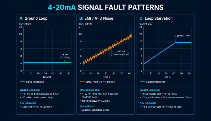
- Symptom A: Constant Positive or Negative Offset (e.g., Reading 4.6 mA at Zero State): This is the hallmark signature of a Ground Loop. An external path is feeding current into the 250 Ω input resistor of the PLC card. If re-zeroing the transmitter temporarily hides the error, the offset will return the moment nearby machinery activates.
- Symptom B: Rapid Oscillating or Hunting Readings (Fluctuating ±0.5 mA): Indicates Electromagnetic Coupling or power supply ripple. This commonly happens when switching power supplies suffer from degraded filter capacitors or when cables run parallel to high-amp busbars.
- Symptom C: Transmitter Ceiling Flatlining (Signal Never Exceeds 14–17 mA): Represents an Insufficient Loop Power / Excessive Burden failure. The transmitter tries to pull 20 mA, but the combined resistance of the wiring and safety barriers drops voltage below the transmitter’s minimum operating threshold (typically 10.5 V to 12 V DC).
To prove conclusively whether the distortion is created by the field transmitter, field wiring, or the control room receiving card, follow this standardized isolation protocol.
3. Step-by-Step Diagnostic Workflow: The “Divide & Conquer” Loop Test
The most effective troubleshooting method is breaking the circuit at the central marshalling terminal block. This separates the field environment from the automated control backplane, isolating the root cause in minutes.
Step 1: Test the DCS/PLC Input Channel with an Independent Source
Disconnect the field cable leads from the marshalling cabinet terminal blocks. Using a precision calibrator like the Fluke 789, configure the meter into Source Mode (Output mA) and inject calibrated step currents (4.00 mA, 12.00 mA, and 20.00 mA) directly into the PLC input terminals.
- If SCADA reads stable and clean: The control room I/O card, safety barrier, and DCS scaling are 100% healthy. The fault is definitely located in field cabling, environmental noise, or the field instrument.
- If SCADA continues to hunt or drift: The fault is inside the panel (defective input card, corrupted ADC filter, or internal cabinet power supply ripple).
Step 2: Energize the Field Transmitter Locally (Cold Loop Test)
Proceed to the field instrument location. Disconnect the plant loop wiring at the transmitter terminal head. Switch your Fluke 789 to Loop Power Mode (24V DC Source + Measure mA) and connect the test leads directly across the transmitter terminals.
- If the local transmitter output is rock-solid at 4.000 mA: The transmitter electronics and sensor element are completely intact. The noise was entering via the field cable run (EMI coupling, shielding breach, or a ground loop across the cable sheath).
- If the local transmitter output drifts or jumps: The transmitter’s internal electronics or terminal diaphragm have failed, or the internal sensing capsule is shorted to the pipe housing.
Step 3: Measure Loop Resistance and Cable Insulation
De-energize the entire loop and short the wires together at the field transmitter. At the marshalling panel, measure total loop DC resistance with a precision multimeter. The value should match theoretical copper resistance based on wire gauge and length. Then, use an insulation tester to confirm insulation resistance exceeds 50 MΩ to earth ground.
For technicians conducting these tests, understanding the nuances of process calibrators makes the difference between swift diagnosis and prolonged downtime.
Need a detailed breakdown of sourcing, simulating, and powering unenergized 2-wire loops? Read our comprehensive laboratory test: Fluke 789 ProcessMeter Hands-On Engineering Review.
4. Shielding & Grounding Architecture: The Single-Point Earth Ground Rule
Improper grounding of twisted-pair instrument cable shields is responsible for more than 70% of persistent industrial noise complaints. Implementing rigorous grounding hygiene permanently resolves spurious signals without requiring costly redesigns.
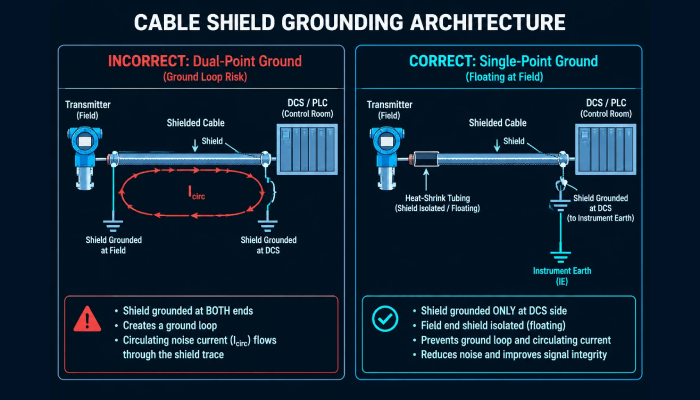
- The Golden Rule: Ground the Shield at ONE End Only: Cable shields (drain wires) must be connected to an instrument clean earth (IE) busbar at the control panel or marshalling cabinet only. The shield at the field transmitter terminal head must be trimmed back, insulated with heat-shrink tubing, and left completely floating.
- The Penalty of Double Grounding: Grounding the shield at both the field transmitter housing and the control room panel creates an intentional conductor path between two physical plant structures. Earth potential differences cause heavy 50/60 Hz stray currents to flow through the shield foil, magnetically inducing severe noise into the signal conductors inside.
- Twisted-Pair Pitch Integrity: Always specify high-quality twisted shielded pair (STP) cables. The tight twist ensures that external magnetic fields induce identical, balanced voltages in both conductors, allowing the receiving differential amplifier to reject the common-mode noise completely.
- Galvanic Isolation as the Ultimate Solution: Where field instruments must be grounded to conductive metallic piping (such as electromagnetic flowmeters or grounded thermocouples), insert a 4–20 mA Galvanic Signal Isolator in the marshalling rack to break direct electrical continuity while transferring the signal accurately across an optocoupler or magnetic barrier.
When standard wiring practices are satisfied, selecting the right diagnostic instrument accelerates identifying elusive intermittent faults.
5. Field Fault Matrix & Recommended Diagnostic Instrumentation
Deploying the right piece of test gear ensures safe compliance with IEC standards and preserves calibration traceability during plant turnarounds. The matrix below outlines field failure symptoms alongside the optimal diagnostic hardware.
| Failure Mode Observed | Root Electrical Cause | Recommended Test Instrument | Practical Value in Field Operations |
|---|---|---|---|
| Constant DC mA Offset | Ground loop current via dual-grounded shields | Fluke 789 ProcessMeter | Slices loop into isolated sections using onboard 24V loop power to pinpoint circulating earth paths. |
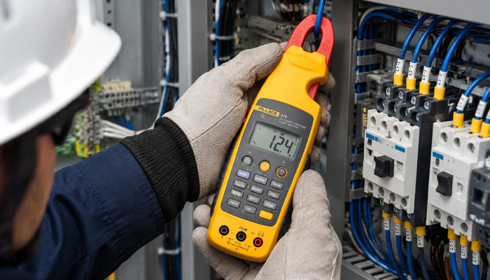
| High-Frequency Hunting | EMI from adjacent VFD motor feeder cables | Fluke 771 / 773 mA Clamp Meter | Measures live 4–20 mA signals non-intrusively without lifting wires or breaking safety critical circuits. |
| Ceiling at 14–16 mA | Excessive burden resistance or weak 24V supply | Fluke 789 ProcessMeter | Tests loop drive capability up to 1200 Ω to confirm whether power supply voltage drops under full 20 mA load. |
| Intermittent Spikes / Dropouts | Degraded cable insulation or junction box moisture | Megger MIT420/2 Insulation Tester | Verifies core-to-core and core-to-shield insulation resistance up to 1000 V to expose water ingress in trays. |
| Dropped HART Communication | Missing series load impedance or noisy carrier | Fluke 789 with Built-in 250 Ω | Toggles an internal 250 Ω load resistor instantly, guaranteeing clean digital polling for handheld communicators. |
Equipping maintenance engineering crews with certified testing gear eliminates guesswork and accelerates facility uptime.
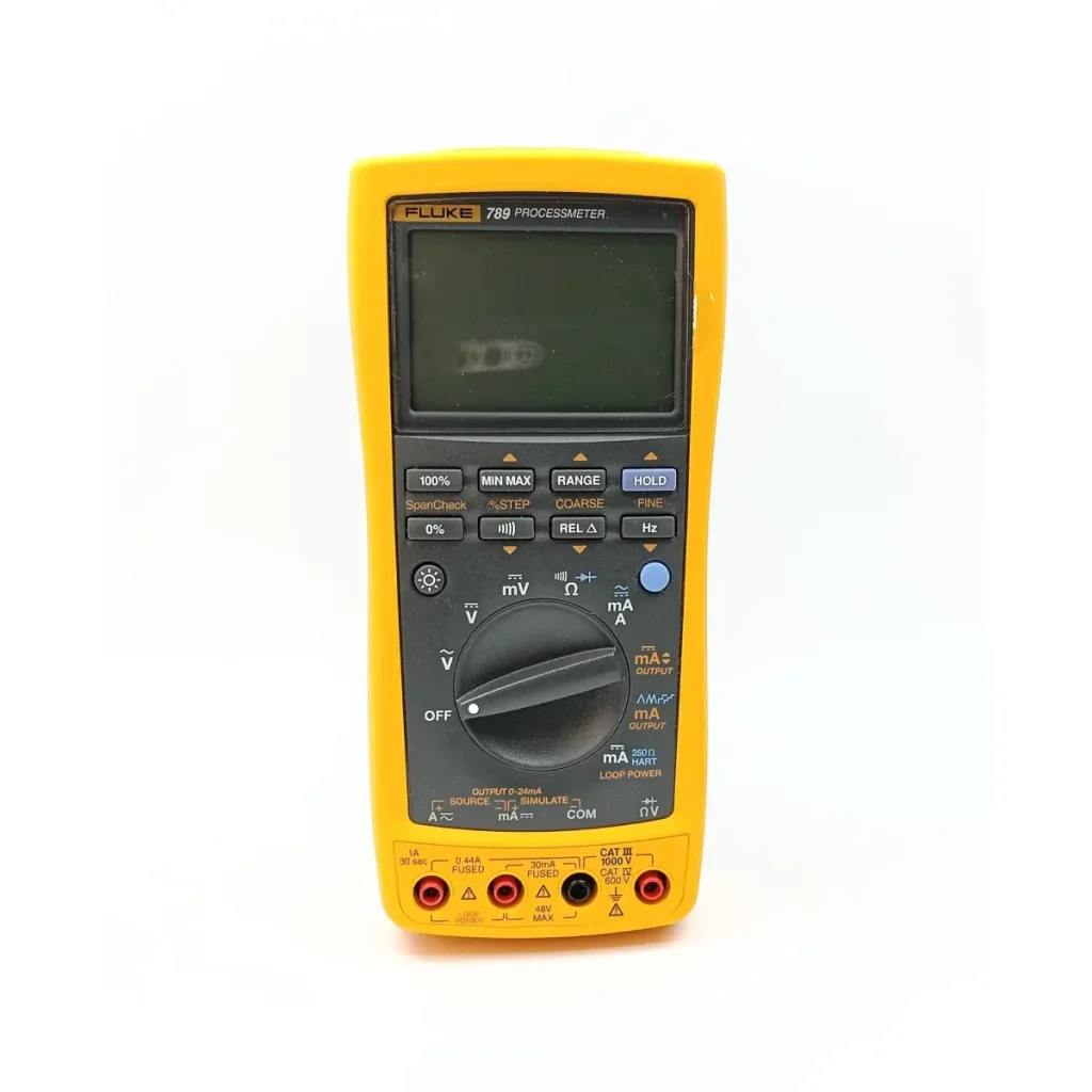
Fluke-789/E Process Meter
Call for price
- Specifications
- Current measurement: Range
- Resolution: 1 mA
- Accuracy: 0.2% + 2 LSD (DC)
- Ran...More info
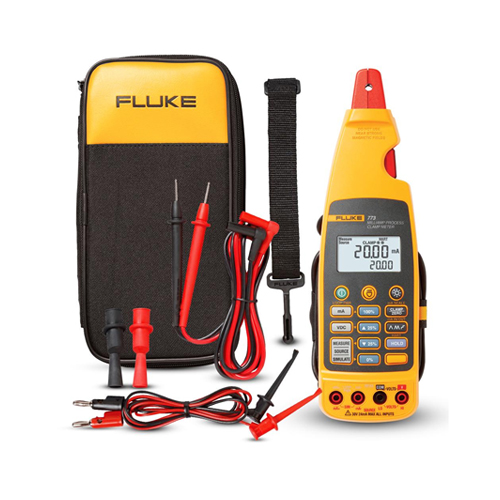
Fluke 773 Milliamp Process Clamp Meter
Call for price
- Measures 0-20mA DC current
- 0-30V voltage range
- 1 kg compact design
- Process calibrator functionality
- Multi-rang...More info
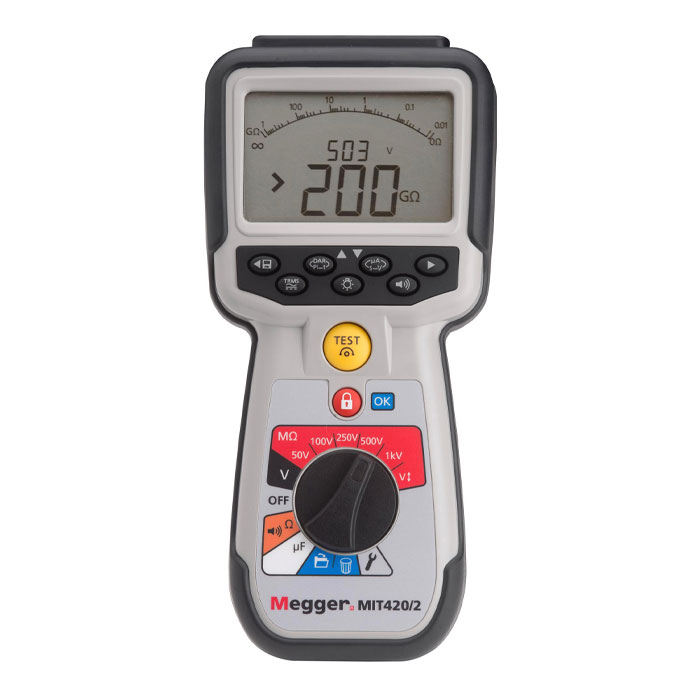
Megger MIT420/2 Insulation Tester
AED 3,265 (excl.VAT)
The Megger MIT420/2 is a CAT IV 600 V insulation and continuity tester with 50–1000 V test voltages, insulation to 200 GΩ, PI/DAR diagnostics and on-b...
More infoExploring genuine process calibrators, loop simulators, and high-precision field multimeters? Browse our authorized regional collection in the MME Process Calibration Instruments Portal.
Why is my 4–20 mA loop reading 4 mA when the process variable is above zero?
A constant 4.00 mA reading despite process changes usually indicates that the transmitter has encountered a hardware fatal error, the sensing impulse line is completely plugged, or the device is stuck in an internal manual test mode. Use a field communicator across a 250 Ω resistor (or activate the HART mode on your Fluke 789) to interrogate the transmitter error log directly.
How much AC voltage ripple is acceptable in a DC current loop?
In a well-designed 24 V DC industrial loop, AC ripple across the load resistor should not exceed 10 mV RMS (equivalent to approximately 0.04 mA of current disturbance across a 250 Ω resistor). If your True-RMS multimeter reads AC ripple greater than 50 mV across the loop terminals, suspect either a failing power supply capacitor bank or strong inductive coupling from high-voltage cables.
What happens if the loop resistance is higher than the power supply capability?
When loop resistance is too high, the circuit suffers from "current clipping." The loop may operate accurately between 4 mA and 14 mA, but as current demand increases toward 20 mA, the required voltage drop exceeds the power supply's output voltage. The signal flattens out, causing the DCS to display lower readings than actual process levels—creating dangerous conditions during overpressure or tank overfill events.
Can I measure 4–20 mA current without breaking the circuit in live facilities?
Yes. In mission-critical facilities where lifting a wire trips an emergency shutdown interlock, technicians use specialized milliamp clamp meters like the Fluke 771 or Fluke 773. These use high-sensitivity Hall-effect magnetic sensors to measure loop currents down to 0.01 mA without disconnecting terminal screws or interrupting continuous plant operations.
 Bench Multimeters