


Featured Multimeters
Featured Clamp Meters
FLIR TG165-X Thermal Camera
Rated 5.00 out of 5
Hioki IR4056-20 Insulation Tester
$0.00 (excl.VAT)Megger Mit525 UK Insulation Resistance Tester
$0.00 (excl.VAT)Featured Thermal Camera
FLIR TG165-X Thermal Camera
Rated 5.00 out of 5
Everything about multimeters

Everything about multimeters starts with understanding their role in electrical measurements. Have you ever needed to check a circuit, measure the voltage of a battery, or diagnose an electrical issue? In such cases, a digital multimeter (DMM) is your best tool. This essential device is widely used in electronics and electrical engineering to measure voltage, current, resistance, and circuit continuity.
Using a multimeter is not just about measuring values; everything about multimeters revolves around their ability to troubleshoot and repair electrical devices. Whether you are a professional engineer or a beginner interested in fixing your own gadgets, learning how to use a multimeter is a crucial skill.
What Is a Multimeter?
A multimeter combines the functionality of several standalone tools: a voltmeter, ohmmeter, and ammeter.Most models measure DC/AC voltage, DC/AC current, and resistance. Many also include advanced tests like continuity, diode checks, and non-contact voltage (NCV). These tools are used to troubleshoot circuits, measure passive components, and verify electrical system integrity.
In the realm of electrical measurements, a versatile and indispensable tool takes center stage – the multimeter. This introductory guide delves into the fundamental aspects of multimeters, shedding light on their purpose, function, and the diverse types that cater to various applications.
Understanding the Purpose and Function of Multimeters
At its core, a multimeter is a sophisticated measuring instrument that allows engineers, technicians, and enthusiasts to gauge a spectrum of electrical properties with precision. It serves as an all-in-one solution, capable of measuring voltage, current, and resistance. By offering a comprehensive view of these essential parameters, multimeters empower professionals to diagnose, troubleshoot, and design electrical systems with unmatched accuracy.
Types of Multimeters and Their Applications
Multimeters come in a variety of types, each tailored to specific applications and environments. The choice of multimeter depends on factors such as measurement requirements, precision, and the intended use case. Here are some common types of multimeters and their applications:
Analog Multimeters
Digital Multimeters
Auto-Ranging Multimeters
Clamp Meters
Benchtop Multimeters
Industrial Multimeters
Wireless Multimeters
Analog Multimeters
Analog Multimeters: These traditional multimeters employ a moving pointer over a calibrated scale to display readings. While less precise than their digital counterparts, analog multimeters are still valuable for quick measurements and applications where high precision isn’t essential.
Digital Multimeters
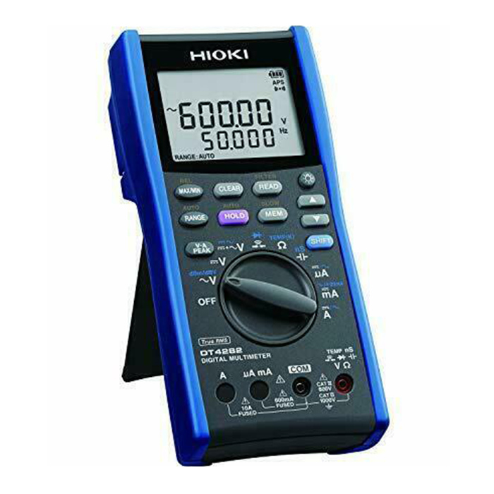
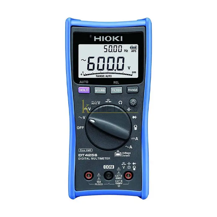
Digital Multimeters (DMMs): Representing a technological leap, DMMs offer numeric displays for accurate and easy-to-read measurements. They have virtually replaced analog multimeters due to their superior precision, versatility, and robustness.
Auto-Ranging Multimeters
Auto-Ranging Multimeters: These advanced DMMs automatically select the appropriate measurement range, simplifying the user’s experience. With auto-ranging, users need not manually adjust settings, making measurements faster and more convenient.
Clamp Meters
Clamp Meters: Designed to measure current in a non-contact manner, clamp meters are ideal for applications where breaking the circuit for measurement is not feasible. They encircle the conductor, offering accurate readings without disrupting the circuit.
Benchtop Multimeters
Benchtop Multimeters: These high-precision instruments are commonly found in laboratories and engineering environments. Benchtop multimeters offer exceptional accuracy and a wide range of measurement options, making them indispensable for research and development.
Industrial Multimeters
Industrial Multimeters: Built to withstand harsh industrial environments, these multimeters are rugged and durable. They cater to professionals working in manufacturing, automation, and heavy industries, where reliability is paramount.
Wireless Multimeters
Wireless Multimeters: Embracing modern connectivity, wireless multimeters enable remote monitoring and data transmission. Engineers can control and view measurements on their smartphones or computers, enhancing convenience and efficiency.
Main Parts of a Digital Multimeter
A multimeter consists of four key components:
The display is where all measurement readings appear. It typically shows four digits, with some models supporting a negative sign to indicate polarity.
🔹 Types of Multimeter Displays:
- Basic LCD Display: Common in entry-level multimeters, showing only numerical values.
- Backlit Display: Found in advanced models, making readings easier in low-light environments.
- Graphical Display (Bar Graph): Present in high-end models to provide a real-time graphical representation of changes in voltage or current.
💡 Tip: If you work in dark areas, consider a multimeter with a backlit display for better visibility.
The selection knob (also called a mode selector) lets users choose different types of electrical measurements, such as:
- Voltage (V): Measures the electrical potential difference between two points.
- Current (A or mA): Measures the flow of electric charge in a circuit.
- Resistance (Ω): Checks how much a component resists current flow.
- Continuity Mode (🔔): Tests if two points in a circuit are electrically connected (if connected, a beep sound is heard).
- Diode Test (▶|◀): Checks if a diode is functional by measuring voltage drop.
✔️ Capacitance Mode (F): Measures the ability of capacitors to store electrical charge.
💡Tip: Some modern auto-ranging multimeters automatically select the correct range for measurement, making them easier to use.
Multimeters have three to four ports, where the probes are plugged in. Choosing the right port is essential for safe and accurate readings.
🔹 Types of Multimeter Ports:
✅ COM (Common) Port:
- This is the ground (negative) connection.
- Always plug the black probe into this port.
✅ mAVΩ Port (Main Input for Most Measurements):
- Used for measuring voltage (V), resistance (Ω), and low current (mA).
- The red probe is connected here for standard measurements.
✅10A Port (For High Current Measurements):
- Dedicated to measuring large currents (>200mA).
- Prevents internal fuse damage when testing high-power circuits.
Important: Always use the correct port! Plugging into the wrong one can damage your multimeter or cause incorrect readings.
Multimeters use two probes to connect to a circuit:
- Black Probe: Always connected to the COM (Common) port.
- Red Probe: Connected to mAVΩ for voltage, resistance, and small currents, or 10A for high-current measurements.
Types of Multimeter Probes
Multimeter probes are essential accessories that allow users to test and troubleshoot electrical circuits accurately. Choosing the right type of probe ensures precise measurements and enhances usability for different testing scenarios. Whether you're working with standard circuits, small IC components, or surface-mounted devices (SMDs), using the appropriate multimeter probe is crucial. Below, we explore the most common types of multimeter probes and their applications.
Standard Test Probes:
These are the most common multimeter probes, used for general circuit testing. They are ideal for measuring voltage (V), current (A), and resistance (Ω) in standard electrical and electronic circuits.
Alligator Clips:
Designed for hands-free connections, these clips allow you to attach the multimeter to larger components, such as batteries, power terminals, and bus bars. Alligator clip probes are useful for long-duration testing, reducing the need to hold the probes manually.
IC Hooks (Integrated Circuit Hooks):
Perfect for testing small IC components and fine circuit points. These probes grip onto tiny IC pins, making them ideal for troubleshooting microcontrollers, sensors, and small electronic components on a PCB (Printed Circuit Board).
Used specifically for SMD (Surface Mount Device) component testing, these probes help measure resistance, capacitance, and diode functionality in miniature circuits. SMD tweezers are especially useful for professionals working on precision electronics and compact PCBs.
- Using the right multimeter probe ensures accurate measurements for different types of circuits.
- Standard probes are suitable for everyday testing, while specialized probes enhance usability in complex applications.
- Hands-free options, such as alligator clips, improve safety and efficiency in electrical measurements.
- Tweezer and IC hook probes are essential for working with small electronic components and high-precision testing.
Selecting the right multimeter probe based on your testing needs can improve measurement accuracy, troubleshooting efficiency, and overall safety when working with electrical and electronic circuits!
Importance of Multimeters in Electrical Work
As a versatile and indispensable tool in the world of electrical engineering, multimeters play a pivotal role in simplifying complex measurements, troubleshooting intricate circuits, and ensuring the safety and efficiency of electrical systems. Whether you're a seasoned electrician or an electronics enthusiast, understanding the significance of multimeters can greatly enhance your ability to work with precision and confidence.
Discover the joy of continuity testing, accompanied by the reassuring buzz of the piezo buzzer. Swiftly identify broken connections and ensure seamless current flow.
Delve into the realm of resistance, with the capability to measure from as low as 10 ohms to the towering heights of 1 Megaohm. Uncover the secrets hidden in resistive pathways.
Journey into the voltage spectrum, with the power to measure from as little as 100mV to a significant 50V. Voltage insights await your exploration.
Explore the realm of AC voltage, spanning from 1V to a towering 400V (or 200V in select regions). Unveil the dynamic nature of alternating current.
Demystify diodes with dedicated testing. Detect faulty diodes and pave the way for accurate circuit analyses.
Basic Principles of Multimeters
Voltage Measurement Techniques
How to Measure Voltage with a Multimeter
Voltage measurement is one of the most fundamental tasks in electrical testing and diagnostics. Whether you’re testing a battery, power supply, or household wiring, knowing how to measure DC and AC voltage using a digital multimeter (DMM) is essential. In this guide, we’ll cover the principles of voltage measurement, the correct way to set up a multimeter, and important safety precautions to ensure accurate and safe measurements.
What Is Voltage and Why Measure It?
Voltage, also known as electromotive force (EMF), represents the electrical potential difference between two points in a circuit. It is the driving force that allows current to flow. Measuring voltage helps diagnose circuit performance, identify faulty components, and verify power supply stability.
🔹 Voltage is measured in volts (V) and follows Ohm’s Law, which states:
V = I × R (Voltage = Current × Resistance)
Voltage Measurement Principles
Voltage measurement relies on a multimeter’s internal circuitry to detect and quantify the difference in electrical potential. A multimeter operates in parallel with the circuit to safely measure voltage without disrupting the current flow.
Types of Voltage:
- DC Voltage (V⎓): Found in batteries, power adapters, and electronic circuits.
- AC Voltage (V~): Found in household outlets, generators, and industrial electrical systems.
Understanding Voltage Measurement Scales
Multimeters offer different voltage ranges, often labeled in volts (V) or millivolts (mV). Users can select an appropriate range based on the expected voltage level:
- Auto-ranging multimeters adjust automatically to display the correct voltage.
- Manual-ranging multimeters require selecting a voltage range higher than the expected value (e.g., 20V for a 12V circuit).
How to Measure DC Voltage (Batteries, Circuits, Power Supplies)
Step 1: Set the Multimeter to DC Voltage Mode (V⎓)
- Turn the selection dial to V⎓ (DC voltage mode).
- If using a manual-ranging multimeter, select the appropriate voltage range.
Step 2: Connect the Multimeter Probes
- Insert the black probe into the COM (Common) port.
- Insert the red probe into the mAVΩ port (for standard voltage measurement).
Step 3: Connect the Probes to the Circuit
- Black probe (COM) → Negative (-) or Ground
- Red probe → Positive (+) terminal
Step 4: Read the Voltage on the Display
- If the probes are reversed, the voltage reading will be negative but still correct.
- A 1.5V AA battery should display around 1.5V, while a fully charged 12V car battery should read around 12.6V.
Connecting a Multimeter for Voltage Measurement
To measure voltage correctly, the multimeter’s probes must be connected across the component or power source:
- The red probe is connected to the higher potential point (positive terminal).
- The black probe is connected to the lower potential point (ground or negative terminal).
A multimeter does NOT interrupt the circuit while measuring voltage—it simply reads the difference in electrical potential between two points.
Common Voltage Measurement Mistakes & Troubleshooting
❌ Multimeter Shows “1” or “OL” (Overload)?
➡️ The selected range is too low; increase the voltage range.
❌Multimeter Shows 0V?
➡️ Ensure the power source is working and probes are correctly connected.
❌ Multimeter Reading Is Unstable?
➡️ Loose connections or fluctuations in AC power could be the cause.
Safety Precautions for Voltage Measurement
- Always use the correct voltage setting (DC or AC).
- Select a higher range if unsure about the voltage level.
- Avoid touching metal parts of probes when testing high voltage.
- For AC voltage, stand on an insulated surface to prevent shocks.
- Do not insert probes into an outlet if unsure of safety procedures.
Key Takeaways
- Voltage measurement is essential for checking circuit performance and diagnosing electrical issues.
- Multimeters operate in parallel with the circuit to measure voltage safely.
- DC voltage is measured in batteries, adapters, and electronic devices, while AC voltage is found in power grids and household outlets.
- Using the correct voltage range ensures accurate readings and prevents overload errors.
- Safety is crucial—use insulated probes, avoid direct contact with high voltage, and follow proper testing procedures.
With these steps, you can confidently measure voltage with a multimeter and troubleshoot electrical circuits with precision!
Current Measurement Techniques
How to Measure Amps with a Multimeter
Measuring current (amps) is essential for diagnosing electrical circuits, testing electronic components, and ensuring that devices operate within safe power limits. Unlike voltage measurement, where the multimeter is placed in parallel, current must be measured in series so that the electric charge flows through the multimeter.
In this guide, we will cover the principles of current measurement, how to correctly set up a multimeter for measuring current, and safety precautions to prevent damage or injury.
What Is Current and Why Measure It?
Current (measured in amperes, A) represents the flow of electric charge through a circuit. It is a key factor in understanding the power consumption of electronic devices and the functionality of circuit components.
🔹 Ohm’s Law states that:
I = V / R (Current = Voltage / Resistance)
This principle helps multimeters measure current by detecting voltage drop across a known internal resistor (shunt resistor) inside the device.
Current Measurement Principles
Multimeters measure current using the current shunt method, where the device calculates the current flow by measuring the voltage drop across a small internal resistor and applying Ohm’s Law.
There are two types of current you may need to measure:
- DC Current (A⎓): Found in batteries, electronic circuits, and automotive systems.
- AC Current (A~): Found in household wiring, appliances, and industrial power systems.
Understanding Current Measurement Scales
Multimeters have different current measurement ranges, usually labeled in:
- Milliamps (mA): Used for measuring low-current circuits (e.g., sensors, small electronic components).
- Amperes (A): Used for higher current applications, such as motors and power circuits.
Auto-Ranging vs. Manual-Ranging Multimeters
- Auto-ranging multimeters automatically adjust to the correct current range.
- Manual-ranging multimeters require you to set the appropriate range based on expected current levels (e.g., 10A for large currents).
How to Measure DC Current (A⎓) with a Multimeter
Step 1: Select the Correct Current Setting
- Turn the multimeter dial to A⎓ (DC Amps mode).
- If using a manual-ranging multimeter, start with the highest range (10A) to prevent overloading.
Step 2: Insert the Probes Into the Correct Ports
- Black probe → COM port (Common)
- Red probe → 10A port (for high current) or mAVΩ port (for low current, below 200mA).
Always begin with the 10A port to avoid blowing the fuse.
Step 3: Break the Circuit and Connect the Multimeter in Series
Unlike voltage measurement, where probes are placed across a component, current must be measured in series:
- Turn off the circuit power before connecting the multimeter.
- Disconnect the circuit at the point where you want to measure current.
- Connect the black probe to one end of the disconnected wire.
- Connect the red probe to the other end, completing the circuit through the multimeter.
- Turn the circuit back on and take the reading.
Step 4: Read the Current Value on the Display
- The reading will appear in amperes (A) or milliamps (mA).
- If the value is too low, switch to a lower range for better precision.
- If the display shows “1” or “OL”, increase the range.
How to Measure AC Current (A~) with a Multimeter
Most standard multimeters cannot measure high AC current directly.Instead, a clamp meter is recommended for safe AC current measurements.
If your multimeter has an AC current mode, follow these steps:
Step 1: Select AC Amps Mode (A~)
- Turn the dial to A~ (AC Amps mode).
Step 2: Insert Probes into the Multimeter
- Black probe → COM port.
- Red probe → 10A port (for high current).
Step 3: Break the Circuit and Insert the Multimeter in Series
- Similar to DC current, disconnect the circuit and place the multimeter in series.
Step 4: Read the Current Value on the Display
- AC current fluctuates, so the reading may not be steady.
- If measuring high AC current (>10A), use a clamp meter for safety.
Measuring AC current directly using standard probes can be dangerous—use a clamp meter for high-power circuits.
Common Current Measurement Mistakes & Troubleshooting
❌ Multimeter Shows “0.00” or Very Low Current?
➡️ You may be measuring in the wrong range – switch to a lower setting (e.g., from 10A to mA).
❌ Multimeter Shows “1” or “OL” (Overload)?
➡️ The selected range is too low, or the current is too high – move to the 10A setting.
❌ Multimeter Fuse Blows?
➡️ You may have exceeded the current limit of the selected port. Replace the fuse and always start with the 10A setting.
❌ Circuit Doesn’t Work After Connecting the Multimeter?
➡️ Make sure the multimeter is properly in series and the circuit is closed after placing the probes.
Safety Precautions for Current Measurement
- Always start with the highest current setting (10A) to avoid overloading the meter.
- Never measure AC current in high-voltage circuits without a clamp meter.
- Do not touch exposed metal parts of the probes while measuring live circuits.
- If unsure about the current level, begin with a high range and adjust accordingly.
- Replace blown fuses only with the correct type specified in the multimeter manual.
Key Takeaways
- Current measurement requires breaking the circuit and placing the multimeter in series.
- Use the correct ports—mAVΩ for low current, 10A for high current—to prevent fuse damage.
- DC current (A⎓) is found in batteries and circuits, while AC current (A~) is found in household wiring.
- Clamp meters are safer for measuring high AC current (>10A).
- Always follow safety precautions to prevent damage to the multimeter and avoid electrical hazards.
With this guide, you can confidently measure current (amps) using a multimeter and troubleshoot electrical circuits safely and accurately!
Resistance Measurement Techniques
How to Measure Resistance with a Multimeter
Measuring resistance is a fundamental aspect of electrical testing and is essential for troubleshooting circuits, testing components, and verifying electrical connections. Resistance, measured in ohms (Ω), represents the opposition to electrical current flow within a circuit.
What Is Resistance and Why Measure It?
Resistance determines how much a material or electrical component limits the flow of electric current. Understanding resistance is crucial for:
- Checking resistors – Ensuring they have the correct resistance value.
- Testing wires and cables – Identifying damaged or broken connections.
- Inspecting fuses – A working fuse should have very low resistance (close to 0Ω).
- Verifying switches and relays – Ensuring they properly open and close.
🔹 Ohm’s Law states:
R = V / I (Resistance = Voltage ÷ Current)
Multimeters use this principle by applying a small voltage to the component and measuring the resulting current to calculate resistance accurately.
Resistance Measurement Scales on a Multimeter
Most multimeters provide resistance measurement options in:
- Ohms (Ω) – The basic unit of resistance.
- Kilohms (kΩ) – 1 kΩ = 1,000 Ω.
- Megohms (MΩ) – 1 MΩ = 1,000,000 Ω.
🔹 Auto-Ranging vs. Manual-Ranging Multimeters
✔️ Auto-ranging multimeters select the appropriate scale automatically.
✔️ Manual-ranging multimeters require choosing a scale slightly higher than the expected resistance value (e.g., use 20kΩ for a 10kΩ resistor).
How to Measure Resistance with a Multimeter
Step 1: Set the Multimeter to Resistance Mode (Ω)
- Turn the selection dial to the Ω symbol (resistance mode).
- If using a manual-ranging multimeter, choose the nearest higher range based on the expected resistance.
Step 2: Insert the Probes Into the Correct Ports
- Black probe → COM port (Common).
- Red probe → mAVΩ port.
Never measure resistance in a powered circuit! Always disconnect power before testing.
Step 3: Disconnect the Component from the Circuit
- Remove the resistor, fuse, or component from the circuit before measuring.
- If in-circuit testing is necessary, ensure the circuit is completely powered off.
Step 4: Connect the Probes to the Component
- Place one probe on each end of the component.
- Ensure good contact between the probes and the component terminals.
Step 5: Read the Resistance Value on the Display
The multimeter will display the resistance value, which may be in:
- Ohms (Ω) for small resistances.
- Kilohms (kΩ) for mid-range resistances.
- Megohms (MΩ) for high resistances.
Common Resistance Measurements & Troubleshooting
Testing a Resistor:
- Compare the measured value with the resistor’s color code or datasheet.
- A 5% tolerance resistor (e.g., 10kΩ ±5%) should read between 9.5kΩ and 10.5kΩ.
Testing a Fuse:
- A good fuse should have very low resistance (close to 0Ω).
- If the multimeter shows “OL” or “1”, the fuse is blown.
Testing a Switch:
- In the closed position, resistance should be 0Ω (or very low).
- In the open position, resistance should be “OL” (open circuit).
Checking a Wire or Cable:
- A working wire should show near 0Ω.
- A broken wire will display “OL” (open circuit).
If testing resistance in a circuit, discharge capacitors, as they can store charge and affect readings.
Common Mistakes & How to Fix Them
❌ Multimeter Shows “OL” or “1” (Overload)?
➡️ The resistance is too high – switch to a higher range.
❌ Multimeter Shows 0Ω When Measuring a Resistor?
➡️ The multimeter may be set to the wrong range – adjust to a lower setting.
❌ Resistance Reading Fluctuates?
➡️ Ensure good contact between the probes and the component.
❌ Measuring Resistance in a Powered Circuit?
➡️ Always disconnect power before measuring resistance to avoid inaccurate readings or damage to the multimeter.
Safety Precautions for Resistance Measurement
- Always disconnect power before measuring resistance!
- Do not touch metal parts of the probes while testing.
- For in-circuit testing, discharge capacitors to prevent false readings.
- If unsure about the expected resistance, start with a high range and adjust accordingly.
Key Takeaways
- Resistance measurement helps diagnose circuit issues and test components.
- Always set the multimeter to Ω mode before measuring.
- Never measure resistance in a powered circuit.
- Auto-ranging multimeters adjust automatically, while manual ones require selecting the correct range.
- Low resistance means good conductivity, while “OL” indicates an open circuit.
Continuity Testing
How to Test Continuity with a Multimeter
Continuity testing is one of the most useful functions of a digital multimeter (DMM) for troubleshooting electrical circuits and checking connections. It helps determine if there is an unbroken electrical path between two points.
A continuity test is particularly useful for:
- Detecting broken wires or PCB traces.
- Checking if fuses, switches, or relays are functioning.
- Verifying proper connections in a circuit.
What Is Continuity?
Continuity means that electricity can flow uninterrupted through a circuit. A good connection has low resistance (close to 0Ω), while an open circuit has infinite resistance (“OL” on a multimeter).
Key Concepts of Continuity Testing
- If the circuit is continuous: The multimeter beeps, indicating a complete electrical path.
- If the circuit is broken: The multimeter shows “OL” (open loop) or a high resistance value, meaning the circuit is not connected.
Continuity is measured with low voltage and low current, so it’s safe to use on most circuits.
How to Test Continuity with a Multimeter
Step 1: Set the Multimeter to Continuity Mode
- Turn the selection dial to the continuity symbol (📶 or a diode symbol).
- Some multimeters automatically select resistance mode (Ω) if they don’t have a dedicated continuity setting.
Step 2: Insert the Probes Into the Correct Ports
- Black probe → COM port (Common).
- Red probe → mAVΩ port.
Step 3: Check if the Multimeter is Working
- Touch the black and red probes together.
- The multimeter should emit a continuous beep, confirming that continuity mode is working.
Step 4: Test the Component or Circuit
- Place one probe on each end of the component or wire you want to test.
- If the multimeter beeps, the circuit is complete (good connection).
- If the multimeter does not beep and shows “OL” (open loop), the circuit is broken.
Common Continuity Tests & Troubleshooting
Testing a Wire or Cable:
- A good wire should beep, indicating a continuous connection.
- A damaged wire will show “OL”, meaning the connection is broken.
Testing a Fuse:
- A good fuse will beep, showing low resistance.
- A blown fuse will not beep and show “OL”.
Testing a Switch:
- In the closed position (ON), the switch should beep.
- In the open position (OFF), there should be no beep (“OL”).
✔️ Testing a PCB Trace:
- Place probes on both ends of a PCB trace. A beep means the connection is intact.
- No beep? The trace may be damaged or broken.
✔️ Testing a Relay or Connector:
- A functional relay or connector pin should show continuity when activated.
- If it does not beep when it should, the component is faulty.
Do not test continuity on a powered circuit, as it can damage the multimeter or give incorrect results.
Common Mistakes & How to Fix Them
❌ Multimeter Does Not Beep on a Known Good Wire?
➡️ Ensure good contact between the probe tips and the wire.
❌ Multimeter Shows “OL” on a Good Component?
➡️ The component may have internal damage—double-check it in isolation.
❌ Testing Continuity on a Powered Circuit?
➡️ Always disconnect power before testing to avoid damage.
❌ Multimeter Beeps but the Circuit Still Doesn’t Work?
➡️ A connection may have high resistance—check with the resistance (Ω) mode.
Safety Precautions for Continuity Testing
- Always disconnect power before testing continuity.
- Never test continuity on live circuits.
- Ensure the probes make proper contact with the component.
- If testing small components, use precision probe tips or alligator clips.
Key Takeaways
- Continuity testing helps check for unbroken connections in a circuit.
- A beep means a complete circuit, while “OL” indicates an open circuit.
- Fuses, switches, wires, and PCB traces can all be tested for continuity.
- Always disconnect power before testing continuity.
testing diodes with a multimeter
Introduction to Resistance Measurement
Resistance measurement involves quantifying the opposition that a component or conductor offers to the flow of current. It’s a crucial parameter in assessing the health of components and identifying faults.
Principles of Resistance Measurement
Multimeters apply a known voltage to the component under test and measure the resulting current. By applying Ohm’s law (R = V/I), the multimeter calculates the resistance based on the voltage and current measurements.
Resistance Measurement Scales
Multimeters offer a range of resistance measurement scales, usually labeled in ohms (Ω) or kilohms (kΩ). The appropriate scale is selected based on the expected resistance value for accurate readings.
Connecting a Multimeter for Resistance Measurement
For resistance measurement, the component or conductor is disconnected from the circuit. The multimeter’s probes are then connected across the component, and the resistance value is displayed on the screen.
Safety Precautions for Resistance Measurement
When measuring resistance, ensure that the component under test is not powered to prevent inaccurate readings or potential damage. It’s essential to choose the correct range and follow safety guidelines.
how to test a battery with a multimeter
Introduction to Resistance Measurement
Resistance measurement involves quantifying the opposition that a component or conductor offers to the flow of current. It’s a crucial parameter in assessing the health of components and identifying faults.
Principles of Resistance Measurement
Multimeters apply a known voltage to the component under test and measure the resulting current. By applying Ohm’s law (R = V/I), the multimeter calculates the resistance based on the voltage and current measurements.
Resistance Measurement Scales
Multimeters offer a range of resistance measurement scales, usually labeled in ohms (Ω) or kilohms (kΩ). The appropriate scale is selected based on the expected resistance value for accurate readings.
Connecting a Multimeter for Resistance Measurement
For resistance measurement, the component or conductor is disconnected from the circuit. The multimeter’s probes are then connected across the component, and the resistance value is displayed on the screen.
Safety Precautions for Resistance Measurement
When measuring resistance, ensure that the component under test is not powered to prevent inaccurate readings or potential damage. It’s essential to choose the correct range and follow safety guidelines.
How to Choose the Right Multimeter

Are you looking for the best multimeter but unsure which one to choose? Whether you're a DIY enthusiast or a professional electrician, selecting the right multimeter depends on accuracy, features, and build quality.
Key Factors to Consider When Choosing a Multimeter
The most important aspect of a multimeter is its accuracy. The level of precision required depends on your use case:
- Basic multimeters have an accuracy of around ±0.5% to ±1%, which is sufficient for home and hobby use.
- Professional multimeters feature True RMS (Root Mean Square) measurement, providing higher accuracy for non-linear AC signals in industrial environments.
True RMS multimeters: Essential for measuring fluctuating AC voltages in complex electrical systems.
Standard multimeters: Suitable for measuring simple DC circuits and household electrical troubleshooting.
A good multimeter should include features that match your specific needs. Some important features to consider are:
- Voltage, Current, and Resistance Measurement – Essential for diagnosing electrical problems.
- Capacitance and Frequency Testing – Useful for electronic circuit analysis.
- Continuity and Diode Testing – Helps identify short circuits or faulty components.
- Auto-ranging Capability – Automatically selects the correct range, making it easier to use.
- Backlit Display – Ensures readability in dimly lit environments.
- Non-Contact Voltage Detection (NCV) – Enhances safety when working with live circuits.
Pro Tip: If you work in high-energy environments, choose a multimeter with Category III or IV safety ratings to protect against power surges.
A high-quality multimeter should be durable, reliable, and meet international safety standards. When choosing a multimeter, check for:
- Shock-resistant housing – Prevents damage from accidental drops.
- Silicone-insulated test leads – Provides enhanced safety and flexibility.
- Overload protection – Prevents damage when measuring high voltages or currents.
- CAT III or CAT IV safety rating – Ensures protection in industrial and high-energy environments.
About the Author :

Mahboobe jahebi
I’m Mahboubeh Jahebi, a content writer and SEO expert with over 5 years of experience in industrial equipment and precision measurement technologies. I’ve worked with international brands and contributed to the content strategy of Mohammad Mahdi Electronics (MME), a leading supplier of test instruments in the Middle East.


 Bench Multimeters