
Megger MIT515 Insulation Resistance Testers
$0.00 (excl.VAT)FLIR TG165-X Thermal Camera
Hioki IR4056-20 Insulation Tester
$0.00 (excl.VAT)FLIR TG165-X Thermal Camera
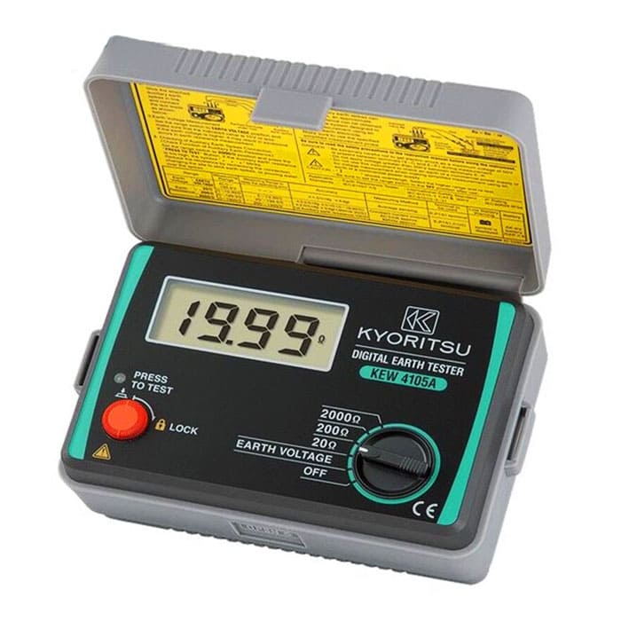
How to Measure Earth Resistance Using an Earth Tester

Accurately measuring earth resistance is vital for ensuring electrical systems are safely grounded. Grounding systems prevent electrical faults from causing damage, reduce shock hazards, and maintain the proper operation of sensitive equipment. An earth tester is a specialized device used to measure this resistance, employing different methods depending on the site conditions and measurement requirements. Below, we explore four key techniques for measuring earth resistance: stakeless testing, selective testing, soil resistivity testing, and fall-of-potential testing.
1. Stakeless Testing
Stakeless testing, also known as clamp-on testing, is a convenient method that eliminates the need for driving auxiliary stakes into the ground. This method is ideal for urban areas or locations where physical access to the ground is limited.
How it Works:
- An earth tester with a clamp-on probe is used to measure earth resistance.
- The clamp is placed around a grounding conductor or rod, and the tester applies an AC signal.
- The tester measures the current and voltage induced by the signal and calculates the resistance based on Ohm’s Law.
Advantages of Stakeless Testing:
- Non-Intrusive: No need for disconnecting the grounding system.
- Quick and Easy: Minimal setup time, making it ideal for routine inspections.
- Urban Suitability: Works well in areas where driving stakes are impractical.
Limitations:
- It may not work effectively for isolated grounding systems.
- Requires a closed-loop system to function accurately.
2. Selective Testing
Selective testing is a method that combines the benefits of stateless testing and traditional methods with auxiliary stakes. It is particularly useful for measuring earth resistance in complex grounding systems without disconnecting them.
How it Works:
- The earth tester is connected to the grounding system, and auxiliary stakes are driven into the ground at a certain distance.
- A clamp meter is placed around the conductor to measure the current flow without disrupting the system.
- The tester calculates the earth’s resistance by comparing the potential difference with the current flow.
Advantages of Selective Testing:
- Non-Disruptive: Avoids interruption of the grounding system, making it suitable for live installations.
- Accurate Results: Provides reliable measurements even in interconnected systems.
Limitations:
- Requires driving auxiliary stakes, which may be difficult in hard or urban terrain.
- Measurement complexity increases with the number of interconnected systems.
3. Soil Resistivity Testing
Soil resistivity testing is crucial for designing and evaluating grounding systems. It measures the resistivity of the soil, which directly affects the efficiency of a grounding system.
How it Works:
- Four electrodes are driven into the ground in a straight line at equal distances (commonly 1 meter apart).
- The earth tester applies a current through the outer two electrodes and measures the voltage between the inner two electrodes.
- The resistivity (rho ) is calculated using the formula:

The resistivity
Where:
- ( a ) = spacing between the electrodes
- ( R ) = resistance measured
Advantages of Soil Resistivity Testing:
- Design Optimization: Helps determine the most suitable location and configuration for grounding systems.
- Preventive Maintenance: Identifies changes in soil conditions that may affect grounding performance.
Limitations:
- Requires sufficient space to deploy the electrodes.
- Results can vary with soil moisture, temperature, and layering.
4. Fall-of-Potential Testing
The fall-of-potential method is the most traditional and widely used technique for measuring earth resistance. It provides highly accurate results by measuring the voltage drop in the soil.
How it Works:
- Setup: An auxiliary current stake and a potential stake are driven into the ground, forming a straight line with the earth electrode under test.
- Measurement: The earth tester injects current through the electrode and the auxiliary current stake, while the potential difference is measured between the electrode and the potential stake.
- Calculation: The tester calculates the earth’s resistance based on the measured voltage and current.
To ensure accuracy, the potential stake’s position is varied, and measurements are plotted on a graph. The resistance is determined from the plateau of the curve.
Advantages of Fall-of-Potential Testing:
- Highly Accurate: Delivers precise measurements when performed correctly.
- Applicable Anywhere: Suitable for standalone and simple grounding systems.
Limitations:
- Requires significant space for stake placement, typically three to five times the depth of the grounding electrode.
- Time-consuming due to the need for repeated measurements at different stake positions.
Key Considerations for Earth Resistance Testing
Regardless of the method chosen, consider the following factors to ensure accurate measurements:
- Soil Conditions: Moisture content, temperature, and soil type can affect resistance.
- Instrument Calibration: Regularly calibrate your earth tester for reliable readings.
- Proper Connections: Ensure secure and clean connections between the tester, stakes, and grounding system.
By choosing the appropriate testing method and adhering to best practices, you can accurately measure earth resistance, ensuring the safety and efficiency of your electrical systems.
Ground Testing Requirements: Achieving Optimal Ground Resistance
When evaluating ground systems, the ideal ground resistance is zero ohms, though this is rarely achievable in practice. Industry standards set by the National Fire Protection Association (NFPA) and IEEE recommend keeping ground resistance at 5.0 ohms or less. However, the National Electric Code (NEC), specifically section 250.56, allows for a ground resistance value of up to 25.0 ohms, emphasizing the importance of maintaining this benchmark for safety. For facilities with sensitive equipment, such as data centers, the ground resistance should not exceed 5.0 ohms. Ultimately, the goal is to achieve the lowest possible ground resistance within the constraints of physical and economic feasibility.
NEC Ground Electrode Requirements
The NEC specifies that a ground electrode must have a minimum length of 2.5 meters (8 feet) in contact with the soil to establish an effective ground resistance system. However, several factors influence the performance of a ground system:
1. Length and Depth of the Ground Electrode: Doubling the length of the electrode can reduce ground resistance by up to 40%.
2. Diameter of the Ground Electrode: Doubling the diameter results in only a 10% reduction in resistance, making it less impactful than electrode length.
3. Number of Ground Electrodes: Adding multiple electrodes enhances performance, but they must be spaced at a distance at least equal to the depth of the electrodes to maximize their effectiveness.
4. Ground System Design: Systems can range from a single ground rod to more advanced designs like a ground plate, depending on the application.
Proper Spacing of Ground Electrodes
For optimal results, ground electrodes must be spaced appropriately to avoid overlapping spheres of influence. The exact spacing depends on the size and shape of the conductive material used. Proper electrode spacing ensures the accuracy of resistance tests by preventing interference between test stakes and the ground system under evaluation.
By understanding and implementing these guidelines, you can achieve a robust and efficient ground system that complies with safety standards while minimizing resistance.
About the Author :

I’m Mahboubeh Jahebi, a content writer and SEO expert with over 5 years of experience in industrial equipment and precision measurement technologies. I’ve worked with international brands and contributed to the content strategy of Mohammad Mahdi Electronics (MME), a leading supplier of test instruments in the Middle East.








 Bench Multimeters