


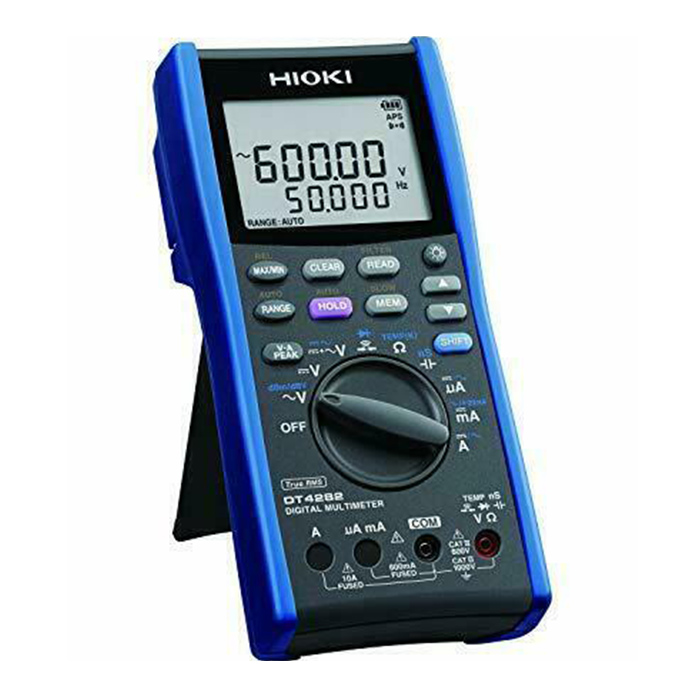


Hioki DT4282 Digital Multimeter
$0.00 (excl.VAT)Hioki Dt4256 Digital Multimeter
$0.00 (excl.VAT)Kyoritsu KEW 1009 Digital Multimeter
$0.00 (excl.VAT)testo 835-T2 – High Temperature IR Thermometer
$2,361.00 (excl.VAT)Testo 175 T1 Temperature Data Logger
$765.00 (excl.VAT)Testo 104-IR Food Safety Thermometer
$687.00 (excl.VAT)testo 830 t1 infrared thermometer
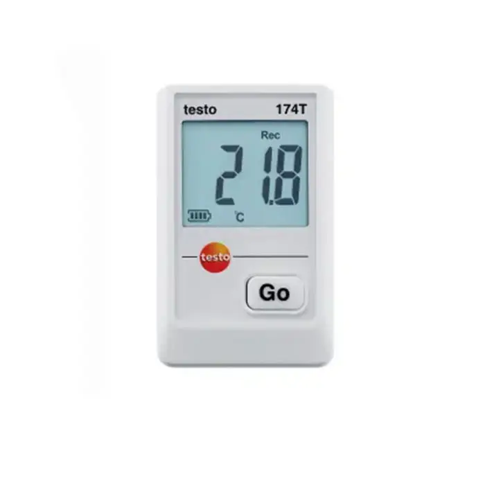
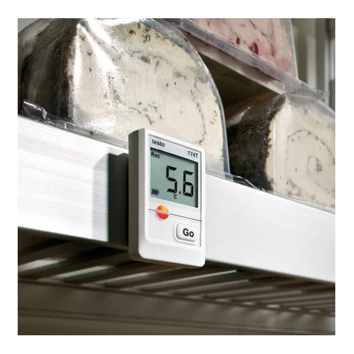
$359.00 (excl.VAT)testo 174 T An Absolute Mini temperature data logger
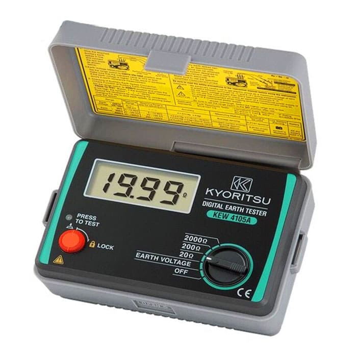
$281.00 (excl.VAT)Kyoritsu KEW 4105A Earth Tester
$0.00 (excl.VAT)Hioki DT4282 Digital Multimeter
$0.00 (excl.VAT)Hioki IR4056-20 Insulation Tester
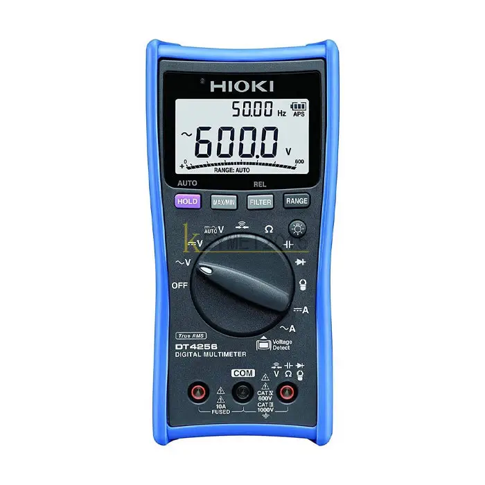
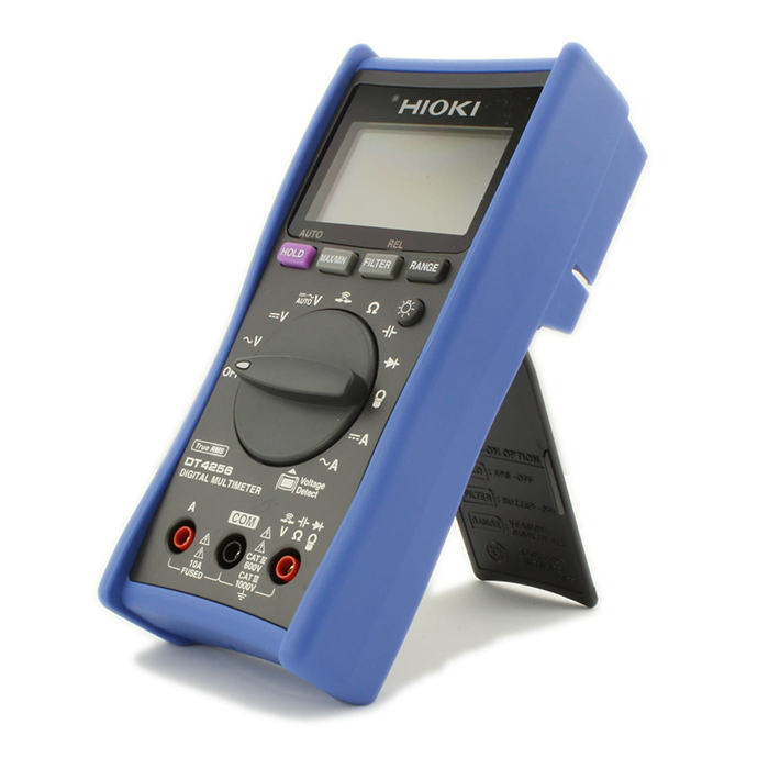
$0.00 (excl.VAT)Hioki Dt4256 Digital Multimeter
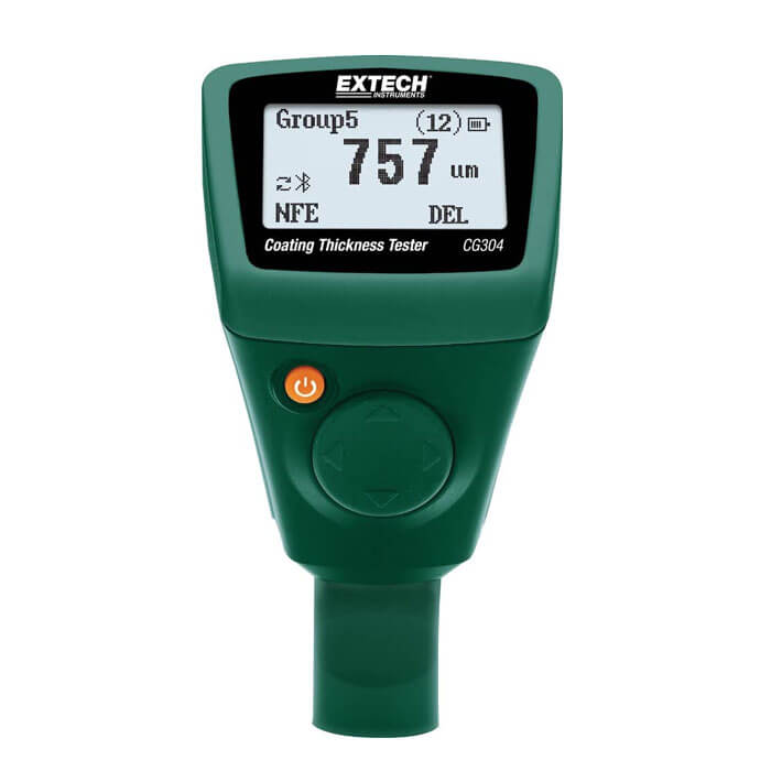
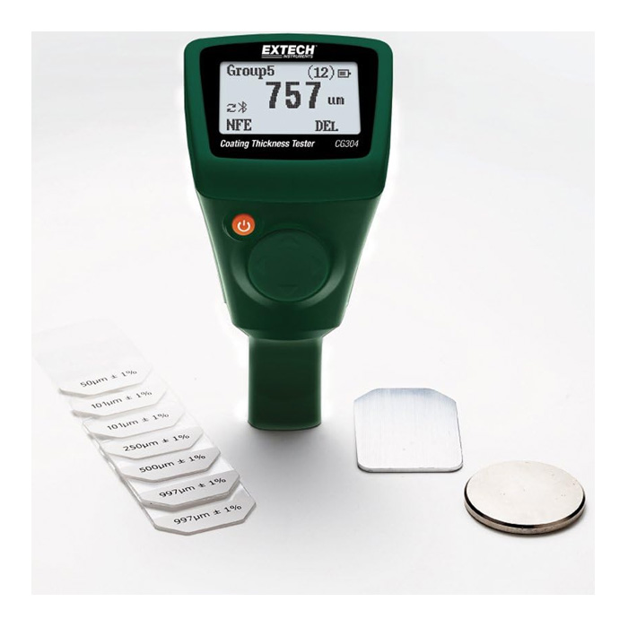
$0.00 (excl.VAT)Extech CG304 Coating Thickness Tester with Bluetooth
$0.00 (excl.VAT)Megger Mit525 UK Insulation Resistance Tester
$0.00 (excl.VAT)
Confused by the symbols on your digital multimeter?
From DC voltage and current to resistance, continuity, and diode testing, each icon on the dial represents a critical measurement mode or function. Whether you're a beginner, electronics hobbyist, electrician, or engineer, this guide will help you clearly understand multimeter symbols—even if you're using an advanced model like a Kyoritsu, Hioki, or Marmonix digital multimeter. Get ready to take safer, more accurate readings across all your electrical systems.
Why Is It Important to Understand Multimeter Symbols?
Using a digital multimeter without understanding its symbols can be risky. A wrong setting might lead to incorrect readings, blown fuses, or even electric shock. For instance, conducting a continuity test while the dial is still on a voltage range could not only result in confusion—it might also damage your circuit.
By learning the essential multimeter symbols—such as those for DC voltage, current, resistance, continuity, and diode testing—you can use professional-grade digital testers more safely and effectively.
This knowledge also makes it easier to interpret circuit diagrams and troubleshoot issues faster, which is a crucial skill for anyone working with electronic or electrical systems.
Multimeter Display and Interface Overview
Before diving into individual multimeter symbols, let’s quickly get familiar with the typical layout of a digital multimeter. Most handheld units share the same four core components that allow for precise and safe electrical measurements. A multimeter typically has four core elements:
| Element | Description |
|---|---|
| Display | Shows real-time readings and status indicators |
| Rotary Dial | Main selector for functions like voltage, current, resistance, etc. |
| Ports (Jacks) | COM (black), VΩ (red), and separate current jacks like mA or A |
| Buttons | Utility functions such as HOLD, REL, MAX/MIN, Hz/% etc. |
Voltage Measurement Symbols
| Symbol | Meaning |
|---|---|
| V⎓ | DC voltage (Direct Current Voltage) |
| mV⎓ | Low DC voltage (millivolts) |
| V~ | AC voltage (Alternating Current Voltage) |
| mV~ | Low AC voltage (millivolts) |
Voltage is one of the most commonly measured electrical parameters, and your digital multimeter offers several symbol options to help you measure it accurately. Whether you're working with DC voltage from a battery or AC voltage from a wall outlet, knowing the correct multimeter symbols for voltage ensures safe, precise readings. In this section, we’ll explain the key voltage measurement symbols you’ll find on most multimeters—starting with DC voltage (V⎓) and AC voltage (V~)—and how to use them effectively in real-world applications.
dc voltage symbol on a multimeter: V⎓

The symbol for DC voltage is typically shown as a capital "V" with a solid line and a dashed line above it, or sometimes as V⎓ or V– . This symbol indicates that the multimeter is set to measure direct current (DC) voltage. DC voltage is found in sources where polarity remains constant, such as batteries, solar panels, automotive systems, and most electronic devices.
AC Voltage Symbol on Multimeter: V~
The symbol for AC voltage is usually represented by a capital "V" alongside a tilde (~), indicating the alternating nature of the current. The wavy line symbolizes the periodic reversal of direction, typical of AC systems following a sine wave pattern. This setting is used for measuring voltages in household outlets and other AC-powered equipment. Some multimeters combine AC and DC voltage on the same setting, requiring a mode switch, while others clearly distinguish AC using the ~ symbol.

AC Millivolts Symbol on Multimeter:(mV~)

Some multimeters offer a dedicated setting for measuring very small AC voltages, represented by mV~ . This setting is designed for precise measurements in the millivolt range, often needed when working with delicate electronic sensor outputs or low-level audio signals.
AC Current Symbol in Multimeter: A~
The symbol A~ represents the AC current mode, indicated by the wavy line . While not all basic multimeters can directly measure AC current (some require a clamp accessory), many do offer a limited AC current function.

Milliamp and Microamp Symbol in Multimeter:(mA/µA)

Multimeters often include finer ranges for measuring smaller currents: milliamps (mA) and microamps (µA) . These allow for more precise measurements of small current flows that would not register accurately on higher ampere settings.

Resistance, Continuity, and Diode Test Functions
| Symbol | Meaning |
|---|---|
| Ω | Resistance measurement (Ohms) |
| 🔔 or ))) | Continuity test (beeps if circuit is complete) |
| ▶| | Diode test (forward voltage drop check) |
Multimeters provide several functions to test the integrity of circuits and components. Resistance, continuity, and diode test modes are usually located close together on the dial, as all relate to how electricity flows—or fails to flow—through a material. The key symbols include Ω for resistance, a diode icon for diode tests, and a speaker or sound wave symbol for continuity.
Resistance Symbol in Multimeter: (Ω Symbol)

Resistance is measured using the Ω (ohm) symbol, representing the object's opposition to current flow.
Frequency and Duty Cycle Measurements
Modern digital multimeters often include functions for measuring signal frequency (Hz) and duty cycle (%), especially if they have a built-in frequency counter for AC voltage signals or a dedicated Hz setting.
Frequency Symbol in Multimeter: (Hz Symbol)

Frequency, expressed in hertz (Hz), indicates the number of cycles per second in an AC signal or pulse train. Some multimeters show a Hz marking near the AC voltage range, while others have a separate setting specifically for frequency. Often, frequency measurement is activated by selecting AC voltage and pressing a secondary button labeled "Hz." Certain models may even have a dedicated Hz/% dial position.
Temperature Symbol in Multimeter:(°C / °F )

Many digital multimeters can also measure temperature using a thermocouple probe, usually indicated by a thermometer symbol or °C/°F marking on the dial.
Low-Pass Filter (LPF) for AC Measurements
Advanced meters may include a Low-Pass Filter (LPF) mode, useful for measuring AC signals that are not pure sine waves, such as the outputs from variable frequency drives (VFDs).
How It Works:
If you see a sine wave symbol combined with "Hz" or "LF," it indicates LPF mode. Activating it filters out high-frequency noise, allowing the meter to accurately read the fundamental 50/60 Hz signal.Use Case:
Essential in industrial settings for accurate voltage or frequency readings on noisy or PWM-shaped signals from motor drives.
Auto-Detect Voltage/Continuity (VCheK™ and Similar Features)
Some multimeters, feature an auto-detect mode like VCheK™, represented by a combined V/Ω symbol. This function automatically identifies whether the circuit has voltage or continuity without manually changing settings.
Tip:
Auto-detect modes are extremely convenient for fast troubleshooting, although there might be a slight delay compared to manually selecting the specific mode. They’re ideal for basic checks like determining whether a wire is live or continuous.
Additional Advanced Features
Certain models may offer even more specialized options, such as:
A square wave output symbol for generating test signals.
A lightning bolt icon to warn of hazardous high voltages.
While not every multimeter will include these features, the functions covered above represent the most common specialized capabilities you'll likely encounter.
Utility Icons and Configuration Buttons in Digital Multimeters
Beyond basic measurement functions, modern multimeters include various utility icons and buttons that enhance the measurement process and user experience.
Hold Function (HOLD)
Many multimeters have a HOLD button or a small icon resembling a hold symbol. Pressing this button freezes the current reading on the display, often indicated by "H" or "Hold" appearing on the screen.
- Usage:
Hold is extremely useful when you cannot easily view the screen while taking a measurement. For instance, you can press HOLD while probing in a tight space, then check the frozen reading afterward. Some models offer an Auto-Hold feature that automatically locks stable readings and emits a beep. - Tip:
Always remember to release the hold function before taking another measurement, or you may mistakenly think your meter isn't updating. - Real-World Example:
When measuring voltage deep inside a car’s engine bay, you use the HOLD feature to freeze the reading, making it easier to retrieve the value (e.g., 13.8V) without needing a second person.
Manual and Auto Range Selection (Range Button)
While most digital multimeters are auto-ranging by default, many include a Range button (often labeled "Range" or with arrow symbols) that allows manual range selection. When auto-ranging is active, "AUTO" usually appears on the screen.
- Usage:
Pressing the range button locks the meter to the current range. Pressing it repeatedly cycles through available ranges, providing a more stable display, especially for fluctuating signals. - Tip:
For everyday measurements, it’s best to return to auto-ranging after manual adjustments. Familiarize yourself with how your meter displays range indicators like "mV," "V," etc. - Real-World Example:
When monitoring a sensor output near 1V, locking the range prevents the meter from constantly shifting decimal places between ranges, making the readings easier to track.
Relative Mode (ΔREL)
Relative mode, indicated by REL or a delta symbol (Δ), allows you to set a temporary zero point based on a reference measurement.
- Usage:
Press REL to store the current reading as zero. Subsequent measurements then display the difference relative to that point—ideal for compensating lead resistance or monitoring small drifts. - Tip:
Remember to deactivate REL mode when moving to a new type of measurement to avoid confusion from the offset. - Real-World Example:
When measuring 1Ω shunt resistors, using REL mode subtracts probe resistance from your measurements, ensuring higher accuracy when checking for resistors that are out of specification.
Min/Max Capture
Many multimeters include a MIN/MAX button that records the highest and lowest values measured over time.
- Usage:
Press MIN/MAX to start recording. Subsequent presses display the minimum or maximum captured value. Holding the button typically exits the mode. - Tip:
Be aware that min/max response time can vary; basic models might miss very fast transients, while advanced ones offer peak capture capabilities. - Real-World Example:
Monitoring the voltage sag when a refrigerator compressor starts up reveals a minimum reading of 112.5V (compared to 120V nominal), helping assess circuit stability under load.
Backlight (Bulb Icon)
A backlight button, often marked with a bulb icon or labeled "Light," illuminates the LCD for easier reading in dim conditions.
- Note:
Backlights often turn off automatically after a short period to preserve battery life. Extended use can drain the battery faster, so use it as needed.
Low Battery Indicator (Battery Symbol)
A battery icon appears on the display when the meter’s battery is running low. When active, measurements—especially resistance readings—may become unreliable.
- Tip:
Keep spare batteries handy. If readings seem unusual or the display dims, check for the battery icon first to avoid chasing false issues.
Other Display Indicators and Icons
Modern multimeters use various on-screen indicators to communicate additional information:
- OL or 1.: Overload or out-of-range warning, often seen in resistance or voltage measurements.
- Negative Sign (-): Indicates reverse polarity during DC measurements.
- Unit Prefixes: Symbols like m (milli), µ (micro), k (kilo), M (mega) show reading scales.
- AC/DC Symbols: Visual indicators to show whether the meter is measuring AC (sine wave) or DC (straight line).
- Speaker Icon: Lights up during continuity tests when the beeper is enabled.
- Lightning Bolt (⚡): Warns of potentially dangerous high voltages.
Understanding these icons helps you accurately interpret your multimeter's readings and avoid potential mistakes during testing.
Confused by the options? Let us help you choose the perfect model. Click here to open popup
What are symbols on a multimeter?
Symbols represent measurement modes like V~ (AC voltage), V⎓ (DC voltage), A~ (AC current), A⎓ (DC current), Ω (resistance), →|— (diode test), 🔊 (continuity), Hz (frequency), and F (capacitance).
How do you use a multimeter for beginners?
Select the measurement type, connect the black lead to COM and red to the right port, turn the dial to the correct symbol, place the probes, and read the value on the screen.
What do all the settings mean on a multimeter?
Settings correspond to voltage (AC/DC), current (AC/DC), resistance, continuity, diode test, frequency, capacitance, and sometimes temperature or duty cycle.
How do you read a multimeter reading?
Check the number, the unit (V, A, Ω), and prefixes like m (milli), µ (micro), k (kilo), or M (mega). Confirm you're in the correct AC or DC mode.
What is 2000m on a multimeter?
It means 2000 millivolts (mV), or 2 volts. It’s a high-precision range for measuring small voltages.
What is the symbol for continuity on a multimeter?
The continuity symbol usually looks like a speaker or sound wave icon. It triggers a beep if the circuit is continuous.
How to use multimeter to check voltage?
Turn the dial to V⎓ (DC) or V~ (AC), plug black lead into COM, red into V port, and touch the probes to the circuit—then read the voltage on the screen.
How to use multimeter for resistance
Set the dial to Ω, power off the circuit, and place the probes across the component to measure resistance.
How to use reversing meter on a multimeter
Set the multimeter to V⎓; if the reading is positive, polarity is correct—if negative, the probes are reversed.
How to check 240 voltage with a multimeter
Set the dial to AC voltage (V~), insert one probe into each hot slot of the 240V outlet, and read the display. Use caution with high voltage.
what is the diode symbol on a multimeter
The diode test function uses a symbol resembling a triangle pointing to a line. This mode tests diodes, transistors, and LEDs.


 Bench Multimeters