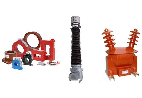
Current transformer &Voltage Transformer Test
In electric power systems, due to the fact that the current of electric voltage in the circuit and system is high, we cannot measure this quantity with simple measuring devices of ammeter and voltmeter. Therefore, in order to measure these quantities, we must use transformer converters called current transformers and voltage transformers.The working principles of voltage current transformers are similar to simple transformers and they work according to the principle of mutual induction.
Current Transformer (C.T):
In power systems, we use a current transformer(C.T) to measure high currents. This current transformer has a primary coil (cable or bus) and a secondary coil (with a large number of turns) which is connected to the current measuring device or ammeter through the secondary Connects.
A current transformer is similar to a step-up transformer.
Voltage Transformer (V.T):
In electrical power systems, we use transformer voltage converters to measure high voltages. Similar to all transformers, this transformer has a primary coil (with a large number of turns) and a secondary coil (with a small number of turns) that is connected to a voltage measuring device or voltmeter Connects.
A voltage transformer works similar to a step-down transformer in electrical systems.
Test types of current and voltage transformers:
1-Ratio Current transformer &Voltage Transformer Test
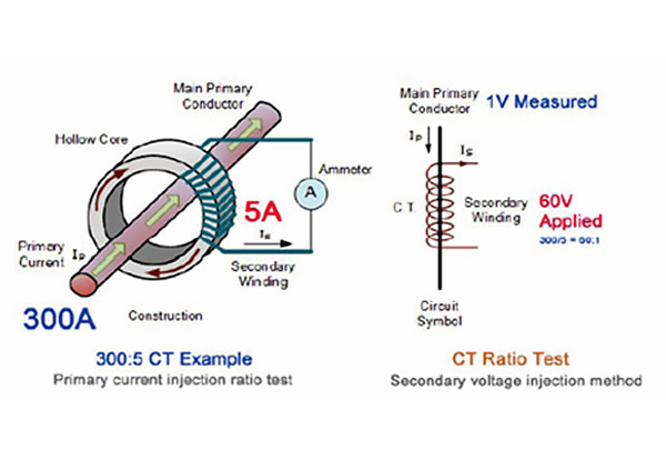
The current transformer has a conversion ratio that indicates the amount of current passing through the primary coil and its ratio through the secondary. For example, in a 300:5 current transformer, if the rated current passes through the primary, the equivalent 5 amps will pass through the secondary. Kord. This is the main relationship of the transfer motor, which is as follows
K=N1/N2=I2/I1=V1/V2
In this test, the primary side of the transformer connected to the current injection device and the current value shown in the ammeter is read by the current changes of the current injection device. With the above conversion ratio written relationship, if the current transformer has no problem, a correct numerical value should be obtained.
The conversion ratio can be obtained in the voltage transformer as well as in the current transformer. First, connect an alternating current voltage to one side of the voltage transformer (secondary or primary) and then connect a voltmeter to the other two ends and obtain the output voltage by dividing these two voltages. The voltage transformer conversion ratio is calculated to each other. Now compare the calculated number with the transformer conversion ratio, it should be equal to each other.
The conversion ratio can be obtained in the voltage transformer as well as in the current transformer. First, connect an alternating current voltage to one side of the voltage transformer (secondary or primary) and then connect a voltmeter to the other two ends and obtain the output voltage by dividing these two voltages. The voltage transformer(v.t) conversion ratio is calculated to each other. Now compare the calculated number with the transformer conversion ratio, it should be equal to each other.
MEGGER INGVAR PRIMARY CURRENT INJECTION TEST SYSTEM(Current transformer &Voltage Transformer Test)
2-Polarity Current transformer &Voltage Transformer Test
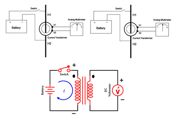
To test the polarity of the current transformer & voltage transformer, connect the primary side or the secondary side to a DC current source and connect an analog voltmeter or galvanometer to the other end of the transformer. Now, by connecting the DC source, if the direction of the galvanometer or voltmeter needle is in the same direction as the polarity of the source,the primary and secondary coils will have the same polarity. The primary and secondary windings will be opposite to each other.
To test the polarity of transformers(C.T)&(V.T), in addition to DC current, we can also determine the polarity with AC current using the circuit shown below.
Primary winding terminals are denoted as A1, A2, and secondary winding terminals are denoted as a1, a2. A voltmeter VA is connected across the primary winding, a voltmeter VB is connected across secondary winding, and a voltmeter VC is connected between primary and secondary winding (between A1 and a1) as shown in the above figure.An autotransformer is used to get variable supply. A Single-phase AC supply is given to the primary winding. And note down the reading of all voltmeters.If the reading of voltmeter VC shows the sum of values VA and VB, the connection of the transformer is in additive polarity. And if the reading of voltmeter VC shows the subtraction of values VA and VB, the connection of the transformer is in subtractive polarity.
Fluke 88V Deluxe Automotive Multimeter
HIOKI DT4281 DIGITAL MULTIMETER
3-Excitation (Saturation) Current transformer &Voltage Transformer Test
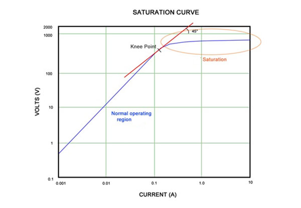
To test the curve and magnetic saturation point of the current transformer or voltage transformer, first connect the secondary or primary coil to an AC current source. Now measure the output voltage of the transformer by changing the source voltage. Continue this until the voltage changes. The transformer current source has increased a lot, but the induced voltage does not increase anymore. This break will be the starting point of the magnetic curve. (For example, if the current increases by 50%, the voltage does not increase by more than 10%).
4-Insulation Resistance Current transformer &Voltage Transformer Test
To test the insulation resistance of the current transformer or voltage transformer, we must use the insulation resistance testing device. We must measure three insulation tests or three insulation resistances of the transformer.
1- Insulation resistance between primary and secondary windings.
2- Insulation resistance between the primary winding and the ground.
3- Insulation resistance between the secondary coil and the ground.
Fluke 1503 Insulation Resistance Meter(Current transformer &Voltage Transformer Test)
5-Winding Resistance Test
To measure the resistance of current or voltage transformer windings, we can use a DC current test or a milliohm measuring device.
6-Winding Resistance Current transformer &Voltage Transformer Test
To measure the resistance of current or voltage transformer windings, we can use a DC current test or a milliohm measuring device.
Megger MOM200A Micro Ohmmeter
6Burden Current transformer &Voltage Transformer Test
The burden of a current transformer can be defined as the total impedance in ohms on the secondary output terminals. The total burden is a combination of impedance offered by watt-hour meter coils, relay current coils, contact resistance, terminal blocks, wire resistance and test switches used in the secondary loop.


